Introduction to the JK Flip Flop
The JK flip flop is a type of bistable multivibrator and one of the most commonly used flip flops in digital electronics. It is a versatile sequential logic circuit that can be used to store a single bit of data. The “JK” in its name stands for Jack Kilby, one of the inventors of the integrated circuit.
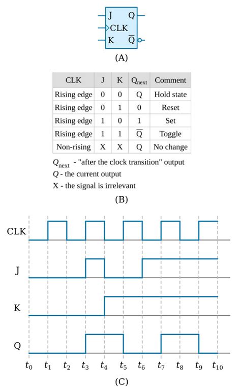
A JK flip flop has two inputs labeled J and K and two outputs labeled Q and Q’. The outputs are complementary, meaning when Q is high (1), Q’ is low (0), and vice versa. The behavior of the flip flop is determined by the truth table, which shows the output states for different combinations of input states.
How a JK Flip Flop Works
The basic operation of a JK flip flop is as follows:
- If J=0 and K=0, the flip flop remains in its current state (no change)
- If J=1 and K=0, the flip flop is set to 1 (Q=1, Q’=0) on the next clock pulse
- If J=0 and K=1, the flip flop is reset to 0 (Q=0, Q’=1) on the next clock pulse
- If J=1 and K=1, the flip flop toggles its state (Q=Q’, Q’=Q) on each clock pulse
The clock input (CLK) is used to synchronize the operation of the flip flop. Changes in the output occur only on the rising edge of the clock pulse, when the clock transitions from 0 to 1.
JK Flip Flop Truth Table
The truth table is a convenient way to summarize the behavior of a JK flip flop for all possible input combinations. It shows the next state of the outputs (Q and Q’) for each combination of current state and inputs (J and K).
| J | K | Q | Q’ | Q(next) | Q'(next) |
|---|---|---|---|---|---|
| 0 | 0 | 0 | 1 | 0 | 1 |
| 0 | 0 | 1 | 0 | 1 | 0 |
| 0 | 1 | 0 | 1 | 0 | 1 |
| 0 | 1 | 1 | 0 | 0 | 1 |
| 1 | 0 | 0 | 1 | 1 | 0 |
| 1 | 0 | 1 | 0 | 1 | 0 |
| 1 | 1 | 0 | 1 | 1 | 0 |
| 1 | 1 | 1 | 0 | 0 | 1 |
From the truth table, we can see that:
- When J=K=0, the flip flop remains in its current state (memory)
- When J=1 and K=0, the flip flop sets to 1
- When J=0 and K=1, the flip flop resets to 0
- When J=K=1, the flip flop toggles its state

JK Flip Flop Circuit Diagram
A JK flip flop can be constructed using NAND gates or NOR gates. The circuit diagram using NAND gates is shown below:
        ___
   J--|    \ |--+-----Q
      |    / |  |
      |  NAND   |
      |       __|__
      +------|     |
   K--|      |/    |---Q'
      |       NAND |
      |______|     |
             |     |
            CLK    |
                   |
                  _|_
                   _
In this circuit, the outputs of the two NAND gates are fed back to the inputs, creating a feedback loop that allows the flip flop to store its state. The J and K inputs are used to control the setting and resetting of the flip flop, while the clock input synchronizes the state changes.

Applications of JK Flip Flops
JK flip flops are widely used in various digital systems for tasks such as:
-
Counters: JK flip flops can be cascaded to create ripple counters, synchronous counters, and ring counters for counting and frequency division applications.
-
Shift Registers: JK flip flops are used as the basic building blocks for shift registers, which are used for serial-to-parallel and parallel-to-serial data conversion, data storage, and delay lines.
-
State Machines: JK flip flops are used to implement state machines, which are sequential circuits that transition between different states based on inputs and current state. State machines are used in control systems, communication protocols, and digital logic design.
-
Frequency Division: By connecting the Q’ output to the J and K inputs, a JK flip flop can be configured as a frequency divider. The output frequency will be half of the input clock frequency.
-
Data Storage: JK flip flops can store a single bit of data, making them useful for temporary data storage in digital systems.

Advantages and Disadvantages of JK Flip Flops
Advantages
-
No invalid states: Unlike other flip flops (such as SR flip flops), JK flip flops have no invalid or undefined states in the truth table.
-
Toggle functionality: The ability to toggle the state when both inputs are high (J=K=1) makes JK flip flops useful for designing counters and frequency dividers.
-
Synchronous operation: JK flip flops are synchronous circuits, meaning state changes occur only on the rising edge of the clock pulse. This makes them less susceptible to noise and glitches compared to asynchronous circuits.
Disadvantages
-
Complexity: JK flip flops are more complex than simpler flip flops like SR and D flip flops, requiring more gates to implement.
-
Power consumption: Due to the increased complexity, JK flip flops may consume more power compared to simpler flip flop designs.
-
Timing constraints: The setup and hold time requirements for the inputs with respect to the clock pulse must be met to ensure proper operation. Violating these constraints can lead to metastability and unpredictable behavior.
Flip Flop Comparison
JK flip flops are just one type of flip flop used in digital electronics. Other common types include:
-
SR Flip Flop: Has two inputs (Set and Reset) and two outputs (Q and Q’). It is the simplest type of flip flop but has an invalid state when both inputs are high.
-
D Flip Flop: Has one input (Data) and two outputs (Q and Q’). The output follows the input on the rising edge of the clock pulse.
-
T Flip Flop: Has one input (Toggle) and two outputs (Q and Q’). The output toggles its state on each rising edge of the clock pulse when the input is high.
The choice of flip flop depends on the specific requirements of the application, such as the need for toggling capability, the presence of invalid states, and the complexity of the circuit.
Frequently Asked Questions (FAQ)
1. What is the difference between a JK flip flop and an SR flip flop?
The main difference is that a JK flip flop has no invalid states in its truth table, while an SR flip flop has an invalid state when both inputs (S and R) are high. Additionally, a JK flip flop has the ability to toggle its state when both inputs (J and K) are high.
2. Can a JK flip flop be used as a toggle flip flop?
Yes, by connecting the Q’ output to both J and K inputs, a JK flip flop can be configured as a toggle flip flop (also known as a T flip flop). In this configuration, the output will toggle its state on each rising edge of the clock pulse.
3. What is the role of the clock input in a JK flip flop?
The clock input is used to synchronize the operation of the flip flop. State changes in the output occur only on the rising edge of the clock pulse, when the clock transitions from low (0) to high (1). This ensures that the flip flop operates synchronously with other parts of the digital system.
4. How can JK flip flops be used to create a counter?
JK flip flops can be cascaded to create various types of counters. For example, a ripple counter can be made by connecting the Q output of each flip flop to the clock input of the next flip flop, with the first flip flop being clocked by the input signal. The J and K inputs of each flip flop are connected to logic high (1) to enable toggling. The output of the counter is taken from the Q outputs of the flip flops.
5. What is the main advantage of using JK flip flops over SR flip flops?
The main advantage of using JK flip flops over SR flip flops is the absence of invalid states in the truth table. In an SR flip flop, when both S and R inputs are high, the output is undefined, which can lead to unpredictable behavior in the circuit. JK flip flops avoid this problem by providing a valid output state for all possible input combinations.
Conclusion
JK flip flops are versatile sequential logic circuits used in a wide range of digital systems. They offer several advantages over simpler flip flop designs, such as the absence of invalid states and the ability to toggle the output state. By understanding the truth table, circuit diagram, and applications of JK flip flops, designers can effectively use them to create counters, shift registers, state machines, and other digital circuits.
As with any digital component, JK flip flops have their own set of advantages and disadvantages that must be considered when choosing the appropriate flip flop for a given application. By comparing JK flip flops with other types, such as SR and D flip flops, designers can make informed decisions based on the specific requirements of their projects.


Leave a Reply