Introduction to IRF840 MOSFET
The IRF840 is a popular N-Channel MOSFET (Metal-Oxide-Semiconductor Field-Effect Transistor) widely used in various electronic applications. It is known for its high power handling capability, fast switching speed, and low on-resistance. In this comprehensive article, we will dive deep into the IRF840 datasheet, exploring its key features, specifications, and applications.
What is a MOSFET?
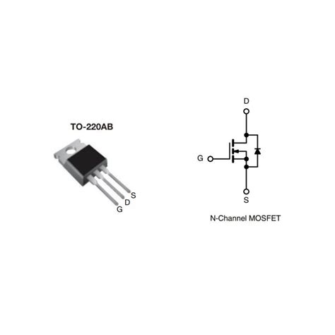
Before we delve into the specifics of the IRF840, let’s briefly understand what a MOSFET is. A MOSFET is a type of transistor that uses an electric field to control the flow of current through a semiconductor channel. It consists of three terminals: the gate, source, and drain. The gate terminal controls the conductivity of the channel between the source and drain terminals.
MOSFETs are widely used in electronic circuits for switching, amplification, and power control applications. They offer several advantages over other types of transistors, such as bipolar junction transistors (BJTs), including higher input impedance, lower power consumption, and faster switching speeds.

Key Features of IRF840 MOSFET
The IRF840 MOSFET boasts several key features that make it a popular choice for various applications. Let’s take a closer look at these features:
1. High Power Handling Capability
The IRF840 is designed to handle high power levels, making it suitable for applications that require significant current and voltage handling. It has a maximum drain-to-source voltage (VDS) rating of 500V and a continuous drain current (ID) rating of 8A. This allows the IRF840 to be used in power switching circuits, motor drivers, and other high-power applications.
2. Fast Switching Speed
One of the notable features of the IRF840 is its fast switching speed. It has a typical rise time (tr) of 35ns and a typical fall time (tf) of 43ns. This fast switching capability enables the IRF840 to be used in high-frequency applications, such as switch-mode power supplies (SMPS) and pulse-width modulation (PWM) control circuits.
3. Low On-Resistance
The IRF840 exhibits a low on-resistance (RDS(on)), which is a critical parameter in power electronics. A lower on-resistance means that the MOSFET can conduct current more efficiently, resulting in lower power dissipation and improved overall efficiency. The IRF840 has a typical RDS(on) of 0.85Ω when the gate-to-source voltage (VGS) is 10V.
4. Wide Operating Temperature Range
The IRF840 is designed to operate over a wide temperature range, from -55°C to +175°C. This makes it suitable for use in various environmental conditions, including industrial and automotive applications where extreme temperatures may be encountered.

IRF840 Datasheet Specifications
Now, let’s dive into the detailed specifications of the IRF840 as provided in its datasheet. Understanding these specifications is crucial for proper circuit design and component selection.
Absolute Maximum Ratings
The absolute maximum ratings specify the limits beyond which damage to the device may occur. These ratings should not be exceeded under any circumstances. Some key absolute maximum ratings for the IRF840 are:
| Parameter | Symbol | Value | Unit |
|---|---|---|---|
| Drain-to-Source Voltage | VDS | 500 | V |
| Gate-to-Source Voltage | VGS | ±20 | V |
| Continuous Drain Current (TC = 25°C) | ID | 8 | A |
| Pulsed Drain Current (tp ≤ 10μs) | IDM | 32 | A |
| Total Power Dissipation (TC = 25°C) | PD | 125 | W |
| Operating Junction Temperature Range | TJ | -55 to +175 | °C |
| Storage Temperature Range | TSTG | -55 to +175 | °C |
Electrical Characteristics
The electrical characteristics provide information about the performance and behavior of the IRF840 under specific operating conditions. Some key electrical characteristics are:
| Parameter | Symbol | Conditions | Min | Typ | Max | Unit |
|---|---|---|---|---|---|---|
| Drain-to-Source Breakdown Voltage | BVDSS | VGS = 0V, ID = 250μA | 500 | – | – | V |
| Gate Threshold Voltage | VGS(th) | VDS = VGS, ID = 250μA | 2.0 | – | 4.0 | V |
| Static Drain-to-Source On-Resistance | RDS(on) | VGS = 10V, ID = 4A | – | 0.85 | 1.2 | Ω |
| Input Capacitance | Ciss | VDS = 25V, VGS = 0V, f = 1MHz | – | 1300 | – | pF |
| Output Capacitance | Coss | VDS = 25V, VGS = 0V, f = 1MHz | – | 180 | – | pF |
| Reverse Transfer Capacitance | Crss | VDS = 25V, VGS = 0V, f = 1MHz | – | 50 | – | pF |
These electrical characteristics provide crucial information for designing circuits that utilize the IRF840 MOSFET. They help in determining the appropriate operating conditions, drive requirements, and performance expectations.

Applications of IRF840 MOSFET
The IRF840 MOSFET finds applications in various fields due to its high power handling capability, fast switching speed, and low on-resistance. Some common applications include:
-
Power Switching: The IRF840 is commonly used in power switching circuits, such as switch-mode power supplies (SMPS), DC-DC converters, and motor drivers. Its high voltage and current ratings make it suitable for controlling high-power loads efficiently.
-
Motor Control: The IRF840 is often employed in motor control applications, particularly in H-bridge configurations for bidirectional motor control. Its fast switching capability allows for precise speed and torque control of motors.
-
Inverters and UPS Systems: The IRF840 is used in power inverters and uninterruptible power supply (UPS) systems. It helps in converting DC power to AC power efficiently and reliably.
-
Automotive Electronics: The wide operating temperature range and high power handling capability of the IRF840 make it suitable for automotive applications. It can be used in electronic control units (ECUs), power management systems, and automotive lighting control.
-
Audio Amplifiers: The IRF840 is sometimes used in the output stage of high-power audio amplifiers. Its low on-resistance and fast switching speed contribute to improved audio quality and efficiency.
FAQs
-
What is the maximum drain-to-source voltage rating of the IRF840?
The maximum drain-to-source voltage rating of the IRF840 is 500V. -
What is the typical on-resistance of the IRF840?
The typical on-resistance (RDS(on)) of the IRF840 is 0.85Ω when the gate-to-source voltage (VGS) is 10V. -
Can the IRF840 handle high currents?
Yes, the IRF840 is designed to handle high currents. It has a continuous drain current rating of 8A and a pulsed drain current rating of 32A. -
Is the IRF840 suitable for high-frequency applications?
Yes, the IRF840 has fast switching speeds, with a typical rise time of 35ns and a typical fall time of 43ns, making it suitable for high-frequency applications. -
What is the operating temperature range of the IRF840?
The IRF840 has a wide operating temperature range from -55°C to +175°C, making it suitable for various environmental conditions.
Conclusion
The IRF840 N-Channel MOSFET is a versatile and high-performance device widely used in power electronics and various other applications. Its high power handling capability, fast switching speed, and low on-resistance make it a popular choice for designers and engineers.
In this article, we explored the key features and specifications of the IRF840 as provided in its datasheet. We discussed its absolute maximum ratings, electrical characteristics, and typical applications. Understanding these specifications is essential for proper circuit design and component selection.
When designing circuits with the IRF840, it is crucial to adhere to the absolute maximum ratings and consider the electrical characteristics to ensure optimal performance and reliability. Proper heat dissipation and protection measures should also be implemented to safeguard the device from potential damage.
The IRF840 MOSFET continues to be a reliable choice for a wide range of electronic applications, offering excellent performance and efficiency. By leveraging its capabilities and understanding its datasheet specifications, designers can create robust and efficient power electronic systems.


Leave a Reply