Introduction to IC4017
The IC4017 is a popular integrated circuit (IC) that functions as a decade counter and Johnson counter. It is widely used in electronic projects and applications that require counting, sequencing, or dividing frequencies. In this comprehensive guide, we will explore the features, pinout, working principle, and various applications of the IC4017.
What is IC4017?
The IC4017 is a 16-pin IC that belongs to the CMOS (Complementary Metal-Oxide-Semiconductor) family. It is a decade counter with ten decoded outputs and a carry-out signal. The IC can count from 0 to 9 and then reset itself to start counting again from 0. It can also function as a 5-stage Johnson counter, providing ten decoded outputs.
Key Features of IC4017
- Decade counter with ten decoded outputs
- 5-stage Johnson counter functionality
- High noise immunity
- Low power consumption
- Wide supply voltage range (3V to 15V)
- Synchronous counting
- Asynchronous reset
- Carry-out signal for cascading multiple IC4017s
IC4017 Pinout and Pin Description
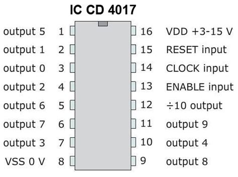
The IC4017 comes in a 16-pin DIP (Dual In-line Package) or SOIC (Small Outline Integrated Circuit) package. The pinout diagram of the IC4017 is shown below:
| Pin Number | Pin Name | Description |
|---|---|---|
| 1 | Q5 | Output 5 |
| 2 | Q1 | Output 1 |
| 3 | Q0 | Output 0 |
| 4 | Q2 | Output 2 |
| 5 | Q6 | Output 6 |
| 6 | Q7 | Output 7 |
| 7 | Q3 | Output 3 |
| 8 | GND | Ground |
| 9 | Q8 | Output 8 |
| 10 | Q4 | Output 4 |
| 11 | Q9 | Output 9 |
| 12 | CARRY | Carry-out |
| 13 | ENABLE | Enable input |
| 14 | CLOCK | Clock input |
| 15 | RESET | Reset input |
| 16 | VDD | Power supply |
Pin Description
- Q0 to Q9: These are the ten decoded outputs of the IC4017. Only one output will be HIGH at a time, while the others remain LOW.
- CARRY: This is the carry-out signal that goes HIGH when the counter reaches the last state (Q9) and can be used to cascade multiple IC4017s for extended counting.
- ENABLE: This input enables or disables the counting operation. When HIGH, counting is enabled, and when LOW, counting is disabled.
- CLOCK: This is the clock input that triggers the counting operation on the rising edge.
- RESET: This input resets the counter to the initial state (Q0) when pulled HIGH.
- VDD: This is the positive power supply pin, typically connected to a voltage between 3V and 15V.
- GND: This is the ground pin, connected to the common ground of the circuit.

Working Principle of IC4017
The IC4017 works on the principle of a decade counter and a Johnson counter. Let’s explore both functionalities in detail.
Decade Counter
In the decade counter mode, the IC4017 counts from 0 to 9 and then resets itself to start counting again from 0. The counting is triggered by the rising edge of the clock input. Each time the clock input goes from LOW to HIGH, the counter advances to the next state, and the corresponding output (Q0 to Q9) goes HIGH while the others remain LOW.
The truth table for the decade counter mode is shown below:
| Clock Pulse | Q0 | Q1 | Q2 | Q3 | Q4 | Q5 | Q6 | Q7 | Q8 | Q9 |
|---|---|---|---|---|---|---|---|---|---|---|
| 0 | 1 | 0 | 0 | 0 | 0 | 0 | 0 | 0 | 0 | 0 |
| 1 | 0 | 1 | 0 | 0 | 0 | 0 | 0 | 0 | 0 | 0 |
| 2 | 0 | 0 | 1 | 0 | 0 | 0 | 0 | 0 | 0 | 0 |
| 3 | 0 | 0 | 0 | 1 | 0 | 0 | 0 | 0 | 0 | 0 |
| 4 | 0 | 0 | 0 | 0 | 1 | 0 | 0 | 0 | 0 | 0 |
| 5 | 0 | 0 | 0 | 0 | 0 | 1 | 0 | 0 | 0 | 0 |
| 6 | 0 | 0 | 0 | 0 | 0 | 0 | 1 | 0 | 0 | 0 |
| 7 | 0 | 0 | 0 | 0 | 0 | 0 | 0 | 1 | 0 | 0 |
| 8 | 0 | 0 | 0 | 0 | 0 | 0 | 0 | 0 | 1 | 0 |
| 9 | 0 | 0 | 0 | 0 | 0 | 0 | 0 | 0 | 0 | 1 |
When the counter reaches the last state (Q9), the carry-out signal goes HIGH, indicating that the counting sequence is complete. The carry-out signal can be used to cascade multiple IC4017s for extended counting beyond 9.
Johnson Counter
In the Johnson counter mode, the IC4017 works as a 5-stage shift register with feedback from the last stage to the first stage. This configuration creates a circular shift register that produces a sequence of ten unique states.
The truth table for the Johnson counter mode is shown below:
| State | Q0 | Q1 | Q2 | Q3 | Q4 | Q5 | Q6 | Q7 | Q8 | Q9 |
|---|---|---|---|---|---|---|---|---|---|---|
| 0 | 1 | 0 | 0 | 0 | 0 | 1 | 0 | 0 | 0 | 0 |
| 1 | 0 | 1 | 0 | 0 | 0 | 0 | 1 | 0 | 0 | 0 |
| 2 | 0 | 0 | 1 | 0 | 0 | 0 | 0 | 1 | 0 | 0 |
| 3 | 0 | 0 | 0 | 1 | 0 | 0 | 0 | 0 | 1 | 0 |
| 4 | 0 | 0 | 0 | 0 | 1 | 0 | 0 | 0 | 0 | 1 |
| 5 | 1 | 0 | 0 | 0 | 0 | 0 | 0 | 0 | 0 | 1 |
| 6 | 1 | 1 | 0 | 0 | 0 | 0 | 0 | 0 | 0 | 0 |
| 7 | 0 | 1 | 1 | 0 | 0 | 0 | 0 | 0 | 0 | 0 |
| 8 | 0 | 0 | 1 | 1 | 0 | 0 | 0 | 0 | 0 | 0 |
| 9 | 0 | 0 | 0 | 1 | 1 | 0 | 0 | 0 | 0 | 0 |
In the Johnson counter mode, the sequence of states is fixed and repeats after ten clock pulses. This mode is useful in applications that require a specific sequence of outputs, such as LED chasing effects or motor control.

Applications of IC4017
The IC4017 finds numerous applications in electronic projects and industrial systems. Some common applications include:
- LED sequencing and chasing effects
- Running light displays
- Frequency dividers
- Stepper Motor control
- Traffic light controllers
- Timing circuits
- Music box sequencers
- Pulse distributors
- Frequency multipliers
- Binary to decimal decoders

Example Circuits using IC4017
LED Chaser
One of the most popular applications of the IC4017 is creating LED chasing effects. In this example, we will create a simple LED chaser using the IC4017 and a 555 timer IC.
Components Required
- IC4017 decade counter
- 555 timer IC
- 10 LEDs
- 10 current limiting resistors (1kΩ)
- 1 capacitor (10μF)
- 1 resistor (1kΩ)
- 1 potentiometer (100kΩ)
- Power supply (5V)
Circuit Diagram
[Insert LED Chaser Circuit Diagram]
Working
- The 555 timer IC is configured in astable mode to generate a clock signal for the IC4017.
- The frequency of the clock signal can be adjusted using the potentiometer.
- The clock signal is fed to the CLOCK input of the IC4017.
- Each output of the IC4017 (Q0 to Q9) is connected to an LED through a current limiting resistor.
- As the IC4017 counts, the LEDs will turn on and off in a sequential manner, creating a chasing effect.
Frequency Divider
The IC4017 can be used as a frequency divider to reduce the frequency of an input signal by a factor of 10.
Components Required
- IC4017 decade counter
- Input signal source
- Power supply (5V)
Circuit Diagram
[Insert Frequency Divider Circuit Diagram]
Working
- The input signal is connected to the CLOCK input of the IC4017.
- The CARRY output of the IC4017 is connected to the RESET input to reset the counter after every ten counts.
- The Q0 output of the IC4017 will have a frequency that is one-tenth of the input signal frequency.
Tips and Tricks for using IC4017
- Use decoupling capacitors (0.1μF) between VDD and GND pins to reduce noise and ensure stable operation.
- Ensure that the input signal levels are within the acceptable range for the IC4017 (VIL < 1.5V, VIH > 3.5V for 5V supply).
- Use appropriate current limiting resistors for LEDs to prevent damage and ensure optimal brightness.
- When cascading multiple IC4017s, connect the CARRY output of one IC to the CLOCK input of the next IC, and tie the RESET inputs together.
- To control the counting speed, adjust the frequency of the clock signal using a potentiometer or a variable oscillator.
Frequently Asked Questions (FAQ)
1. What is the maximum counting frequency of the IC4017?
The maximum counting frequency of the IC4017 depends on the supply voltage. At 5V, the typical maximum frequency is around 5 MHz. However, it is recommended to operate the IC at lower frequencies for reliable operation.
2. Can the IC4017 be used with a microcontroller?
Yes, the IC4017 can be easily interfaced with microcontrollers such as Arduino or PIC. The microcontroller can generate the clock signal and control the RESET and ENABLE inputs of the IC4017 to achieve desired counting sequences.
3. How can I cascade multiple IC4017s for extended counting?
To cascade multiple IC4017s, connect the CARRY output of the first IC to the CLOCK input of the second IC, and so on. Tie the RESET inputs of all ICs together and control them with a single signal. The Q0 to Q9 outputs of each IC will represent a different digit of the count value.
4. What happens if the RESET input is held HIGH?
When the RESET input is held HIGH, the IC4017 will be in a constant reset state, and all outputs will be LOW. The counting operation will not progress until the RESET input is brought LOW.
5. Can the IC4017 be powered by a 3.3V supply?
Yes, the IC4017 can operate with a supply voltage as low as 3V. However, the output voltage levels will also be reduced, and the maximum counting frequency will be lower compared to operation at 5V.
Conclusion
The IC4017 is a versatile and widely used decade counter and Johnson counter IC that offers a range of features and applications in electronic projects. Its ability to count, sequence, and divide frequencies makes it an essential component in many circuits.
By understanding the pinout, working principle, and example circuits discussed in this guide, beginners can easily incorporate the IC4017 into their projects and explore its potential. With its high noise immunity, low power consumption, and wide supply voltage range, the IC4017 is a reliable choice for both hobbyists and professionals alike.
As you delve deeper into the world of electronics, the IC4017 will prove to be a valuable tool in your arsenal, enabling you to create innovative and exciting projects. So, go ahead and experiment with the IC4017, and unleash your creativity in the realm of electronic design!


Leave a Reply