Introduction to the 555 Timer IC and PWM
The 555 timer is one of the most popular and versatile integrated circuits (ICs) of all time. Developed in 1970 by Hans Camenzind at Signetics, the 555 timer can be used to create a variety of timing and pulse generation circuits. One of its most useful applications is generating pulse width modulation (PWM) signals.
What is Pulse Width Modulation?
Pulse Width Modulation, or PWM, is a technique for controlling power delivered to electrical devices, made practical by modern electronic power switches. PWM is used in a wide variety of applications, ranging from measurement and communications to power control and conversion.
PWM works by rapidly switching a power source on and off. By controlling the duty cycle of the signal (the fraction of time that the output is high vs. the total period of the signal), the average power delivered to the load can be precisely controlled. The main advantage of PWM is that power loss in the switching devices is very low.
How the 555 Timer Works in PWM Mode
The 555 timer IC has two basic operating modes:
- Monostable (one-shot) mode
- Astable (free-running) mode
To create a PWM signal, the 555 timer is configured in astable mode. In this mode, the 555 timer will continually oscillate between its high and low states, generating a continuous rectangular wave.
The frequency and duty cycle of this rectangular wave are determined by two resistors (RA and RB) and one capacitor (C). The capacitor repeatedly charges and discharges between 1/3 VCC and 2/3 VCC, while the resistors set the charge and discharge times.
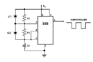
Here is the basic astable configuration for generating a PWM signal with the 555 timer:
[Astable 555 Timer Circuit diagram]
The frequency (f) and duty cycle (D) of the output signal can be calculated using these formulas:
f = 1.44 / ((RA + 2 RB) × C)
D = (RB) / (RA + 2 RB)
By selecting appropriate values for RA, RB, and C, the desired PWM frequency and duty cycle can be achieved.
Designing a 555 PWM Circuit
Step 1: Determine PWM Frequency and Duty Cycle Requirements
The first step in designing a 555 PWM circuit is to determine the required frequency and duty cycle for the application. These parameters will guide the selection of the resistor and capacitor values.
For example, let’s say we want to design a PWM circuit to control the brightness of an LED. We want the PWM frequency to be around 1 kHz to avoid visible flicker, and the duty cycle to be adjustable from 0% to 100%.
Step 2: Select the Capacitor Value
The capacitor value (C) is usually selected first based on the desired PWM frequency. A good rule of thumb is to choose a capacitor that will give a charge/discharge time of about 1/100 of the desired period.
For a 1 kHz PWM signal, the period is 1 ms. So we want the charge/discharge time to be about 10 μs.
Using the capacitor charge time formula:
t = R × C
If we choose a typical capacitor value like 10 nF (0.01 µF), then the total resistance (RA + 2 RB) should be about 1 kΩ to get a 10 μs charge/discharge time.
Step 3: Select the Resistor Values
Once the capacitor value is known, the resistors RA and RB can be calculated using the frequency and duty cycle formulas.
Recall:
f = 1.44 / ((RA + 2 RB) × C)
D = (RB) / (RA + 2 RB)
Solving these equations for RA and RB:
RA = (1.44 / (f × C)) × (1 – D)
RB = (1.44 / (f × C)) × D
For our example with a 1 kHz frequency, 10 nF capacitor, and adjustable duty cycle:
RA = 144 kΩ × (1 – D)
RB = 144 kΩ × D
To make the duty cycle adjustable, we can replace RB with a potentiometer. A 200 kΩ pot would work well here. RA can be a fixed 100 kΩ resistor.
Here’s the resulting circuit:
[555 PWM LED dimmer circuit diagram]

PWM Applications
PWM has a wide range of applications due to its efficiency and precision in controlling power delivery. Some common uses of PWM include:
Motor Speed Control
PWM is commonly used to control the speed of DC motors. By varying the duty cycle of the PWM signal, the average voltage supplied to the motor can be controlled, which in turn controls the motor’s speed.
PWM motor control offers several advantages over analog speed control methods:
- Higher efficiency (less power loss in the control circuit)
- Precise speed control
- Compatible with digital control systems
A typical PWM motor speed control circuit using a 555 timer looks like this:
[555 PWM motor speed control circuit diagram]
LED Dimming
PWM is an effective method for dimming LEDs. By rapidly turning the LED on and off with a PWM signal, the average current through the LED can be controlled, which varies its brightness.
PWM dimming has several benefits compared to analog dimming methods:
- No color shift as brightness is reduced
- Higher efficiency (no power loss in current-limiting resistors)
- Easy to implement with digital control
The 555 timer circuit we designed earlier is an example of a PWM LED dimmer.
Servo Motor Control
Servo motors are a type of motor that can be precisely controlled in position. They are commonly used in robotics, RC vehicles, and industrial automation.
Servo motors are controlled by a PWM signal, where the pulse width determines the servo position. Most servos expect a pulse every 20 ms, with a pulse width between 1 ms and 2 ms.
A 555 timer can be used to generate this PWM servo control signal. Here’s a typical circuit:
[555 servo control circuit diagram]
Voltage Regulation
PWM can also be used for voltage regulation. By varying the duty cycle of a PWM signal driving a switching regulator, the output voltage can be precisely controlled.
PWM voltage regulation is used in a variety of power supply applications, from battery chargers to DC-DC converters.
A basic PWM voltage regulator circuit using a 555 timer and a MOSFET looks like this:
[555 PWM voltage regulator circuit diagram]

Advantages and Disadvantages of 555 PWM
While the 555 timer is a simple and versatile way to generate PWM signals, it has some limitations compared to other methods.
Advantages
- Simple and low-cost
- Robust and reliable
- Wide supply voltage range (4.5V to 16V)
- Can source or sink up to 200 mA
- Easy to configure for different frequencies and duty cycles
Disadvantages
- Fixed frequency (determined by resistor and capacitor values)
- Duty cycle affected by changes in supply voltage
- Limited to relatively low frequencies (typically under 500 kHz)
- Higher power consumption than some dedicated PWM ICs
Despite these limitations, the 555 timer remains a popular choice for many PWM applications due to its simplicity, low cost, and wide availability.

Frequently Asked Questions (FAQ)
1. What is the maximum frequency I can get from a 555 timer PWM circuit?
The maximum practical frequency for a 555 timer PWM circuit is around 500 kHz. At higher frequencies, the 555’s output transistors may not be able to switch fast enough, resulting in a distorted output waveform.
2. Can I use a 555 timer PWM circuit to control an AC device?
No, the 555 timer’s output is DC only. To control an AC device, you would need to use the 555’s PWM output to drive a solid-state relay (SSR) or a TRIAC, which can then switch the AC load.
3. How do I change the duty cycle of my 555 PWM circuit?
To change the duty cycle, you need to adjust the ratio of the resistors RA and RB. Increasing RB relative to RA will increase the duty cycle, while decreasing RB will decrease the duty cycle. The easiest way to make the duty cycle adjustable is to replace RB with a potentiometer.
4. Can I power my 555 PWM circuit from a battery?
Yes, the 555 timer can operate from a supply voltage range of 4.5V to 16V, making it suitable for battery-powered applications. Just make sure your battery can supply enough current for your load.
5. How do I calculate the values of the resistors and capacitor for my 555 PWM circuit?
To calculate the resistor and capacitor values, you need to know your desired PWM frequency and duty cycle. Then use these formulas:
f = 1.44 / ((RA + 2 RB) × C)
D = (RB) / (RA + 2 RB)
Solve these equations for RA, RB, and C based on your frequency and duty cycle requirements. It’s often easiest to start by choosing a standard capacitor value, then calculate the resistors.
Conclusion
The 555 timer is a versatile and easy-to-use IC that can generate PWM signals for a variety of applications. By understanding how to configure the 555 timer in astable mode and select the appropriate resistor and capacitor values, you can design PWM circuits to control motor speed, LED brightness, servo position, and more.
While the 555 timer has some limitations compared to dedicated PWM controller ICs, its simplicity and low cost make it a popular choice for many projects. With its wide supply voltage range and decent output current capability, the 555 timer is well-suited for battery-powered and low-power applications.
Whether you’re a hobbyist or a professional engineer, the 555 timer is a valuable tool to have in your circuit design toolkit. Its flexibility and ease of use make it a great starting point for exploring the world of pulse width modulation.


Leave a Reply