What is I2C?
I2C, also known as I²C or IIC, is a synchronous serial communication protocol developed by Philips Semiconductors (now NXP Semiconductors) in 1982. It is a multi-master, multi-slave protocol that allows multiple devices to communicate on the same bus using only two wires: Serial Data Line (SDA) and Serial Clock Line (SCL).
How I2C Works
In an I2C communication system, each device is assigned a unique 7-bit address. The device initiating the communication is called the master, while the device being addressed is called the slave. The master generates the clock signal and initiates the data transfer. Multiple masters can exist on the same bus, but only one master can control the bus at a time.
The I2C protocol follows a specific sequence of events:
- Start condition: The master pulls the SDA line low while the SCL line remains high, indicating the beginning of a transmission.
- Address and R/W bit: The master sends the 7-bit slave address followed by a single bit indicating whether it wants to read (1) or write (0) data.
- Acknowledgement (ACK): The addressed slave pulls the SDA line low during the 9th clock pulse to acknowledge the reception of the address.
- Data transfer: The master or slave (depending on the R/W bit) sends data one byte at a time, with the MSB (Most Significant Bit) first. Each byte is followed by an ACK bit.
- Stop condition: The master pulls the SDA line high while the SCL line remains high, indicating the end of the transmission.
Advantages of I2C
- Simple wiring: I2C requires only two wires (SDA and SCL) for communication, making it ideal for applications with limited PCB space.
- Addressing: Each device on the I2C bus has a unique address, allowing for easy identification and communication with specific devices.
- Multi-master support: I2C allows for multiple master devices on the same bus, enabling complex systems with multiple controllers.
- Hardware flow control: The ACK bit provides built-in flow control, ensuring that data is not lost during transmission.
Disadvantages of I2C
- Lower speed: I2C is slower compared to SPI, with a maximum clock frequency of 3.4 MHz in high-speed mode and 100 kHz in standard mode.
- Open-drain/open-collector: I2C uses open-drain or open-collector drivers, requiring pull-up resistors on the bus lines, which can limit the bus capacitance and speed.
- No error checking: I2C does not have built-in error checking mechanisms, such as CRC (Cyclic Redundancy Check), which can lead to undetected data corruption.
What is SPI?
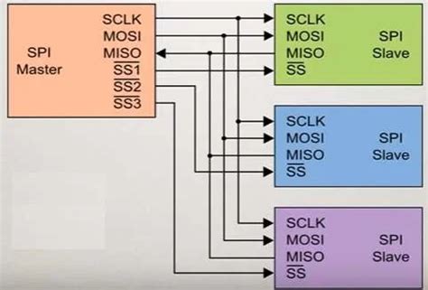
SPI is a synchronous serial communication protocol developed by Motorola in the mid-1980s. It is a full-duplex, single-master, multiple-slave protocol that allows for high-speed data transfer between devices. SPI uses four wires: Serial Clock (SCLK), Master Output Slave Input (MOSI), Master Input Slave Output (MISO), and Slave Select (SS) or Chip Select (CS).
How SPI Works
In an SPI communication system, the master device initiates the communication and generates the clock signal. The master selects the desired slave device by pulling the corresponding SS/CS line low. Data is transferred between the master and slave simultaneously, with the master sending data on the MOSI line and the slave sending data on the MISO line.
The SPI protocol follows a specific sequence of events:
- Slave selection: The master pulls the SS/CS line of the desired slave low, activating the slave device.
- Data transfer: The master generates the clock signal on the SCLK line and simultaneously sends data on the MOSI line. The slave reads the data on the MOSI line and sends data on the MISO line.
- Slave deselection: The master pulls the SS/CS line high, deactivating the slave device.
Advantages of SPI
- High speed: SPI can achieve much higher data transfer rates compared to I2C, with clock frequencies typically ranging from 1 MHz to 100 MHz.
- Full-duplex: SPI allows for simultaneous bidirectional data transfer, enabling faster communication between devices.
- No addressing: SPI does not require device addressing, simplifying the communication protocol and reducing overhead.
- Flexible data format: SPI allows for flexible data formats, as the protocol does not specify a particular format or length for the transferred data.
Disadvantages of SPI
- More wires: SPI requires more wires compared to I2C (four vs. two), which can be a disadvantage in applications with limited PCB space.
- No multi-master support: SPI is a single-master protocol, meaning that only one master device can control the bus at a time.
- No flow control: SPI does not have built-in flow control mechanisms, such as the ACK bit in I2C, which can lead to data loss if the slave is not ready to receive data.
- No error checking: Like I2C, SPI does not have built-in error checking mechanisms, which can lead to undetected data corruption.

Comparing I2C and SPI
Now that we have a basic understanding of how I2C and SPI work, let’s compare the two protocols in terms of their key characteristics.
| Characteristic | I2C | SPI |
|---|---|---|
| Wires | 2 (SDA, SCL) | 4 (MOSI, MISO, SCLK, SS/CS) |
| Speed | Up to 3.4 MHz (high-speed mode) | Up to 100 MHz |
| Addressing | 7-bit device addressing | No addressing, slave selection using SS/CS |
| Multi-master support | Yes | No |
| Flow control | Hardware (ACK bit) | None |
| Data format | 8-bit data format | Flexible data format |
| Error checking | None | None |
| Typical applications | Low-speed peripherals (sensors, EEPROMs) | High-speed peripherals (displays, SD cards, ADCs) |
Speed
SPI is generally faster than I2C, with typical clock frequencies ranging from 1 MHz to 100 MHz. I2C, on the other hand, is limited to a maximum clock frequency of 3.4 MHz in high-speed mode and 100 kHz in standard mode. If high-speed data transfer is a priority, SPI is the better choice.
Wiring
I2C has a distinct advantage over SPI in terms of wiring complexity. I2C requires only two wires (SDA and SCL) for communication, while SPI requires four wires (MOSI, MISO, SCLK, and SS/CS). In applications with limited PCB space or a large number of devices, I2C can be more convenient and cost-effective.
Addressing and Multiple Slaves
I2C uses 7-bit device addressing, allowing for up to 128 unique devices on the same bus. Each device has its own address, making it easy to identify and communicate with specific devices. SPI, on the other hand, does not have built-in addressing. Instead, it uses the SS/CS lines to select the desired slave device. This means that for each additional slave device, an extra SS/CS line is required, which can quickly increase the wiring complexity.
Multi-Master Support
I2C supports multi-master communication, allowing for multiple master devices to control the bus. This feature is particularly useful in complex systems with multiple controllers. SPI, however, is a single-master protocol, meaning that only one master device can control the bus at a time.
Flow Control and Error Checking
I2C has a built-in hardware flow control mechanism in the form of the ACK bit. After each byte is transferred, the receiving device must acknowledge the reception by pulling the SDA line low. This ensures that data is not lost during transmission. SPI does not have any built-in flow control mechanisms.
Neither I2C nor SPI have built-in error checking mechanisms, such as CRC. This means that data corruption can go undetected unless additional error checking measures are implemented at the application level.

Choosing Between I2C and SPI
When deciding between I2C and SPI for your embedded system, consider the following factors:
- Speed requirements: If high-speed data transfer is a priority, SPI is the better choice. If lower speeds are acceptable, I2C can be a more suitable option.
- Number of devices: If your system has a large number of devices, I2C’s addressing feature can simplify wiring and communication. SPI may become cumbersome as the number of devices increases due to the need for additional SS/CS lines.
- PCB space: If PCB space is limited, I2C’s two-wire interface can be more convenient and cost-effective compared to SPI’s four-wire interface.
- Multi-master support: If your system requires multiple master devices, I2C is the only option, as SPI does not support multi-master communication.
- Compatibility: Consider the compatibility of the devices you plan to use in your system. Some devices may only support one protocol or the other.

Real-World Applications
I2C and SPI are widely used in various embedded systems and applications. Here are some examples:
I2C Applications
- Environmental sensors (temperature, humidity, pressure)
- Real-time clocks (RTCs)
- EEPROMs and other memory devices
- LCD and OLED displays
- Power management ICs
- Audio codecs
SPI Applications
- High-speed ADCs and DACs
- SD cards and other storage devices
- Graphic LCDs and TFT displays
- External flash memory
- Wireless communication modules (Wi-Fi, Bluetooth)
- FPGA configuration interfaces
Frequently Asked Questions (FAQ)
-
Can I use I2C and SPI together in the same system?
Yes, you can use both I2C and SPI in the same system. Each protocol has its own set of pins and can operate independently of the other. This allows you to take advantage of the strengths of each protocol for different components in your system. -
Is it possible to convert between I2C and SPI?
Yes, there are bridge ICs available that can convert between I2C and SPI. These devices can be useful when you need to interface components that use different protocols. However, keep in mind that converting between protocols may introduce latency and additional complexity to your system. -
What is the maximum number of devices that can be connected to an I2C bus?
I2C uses 7-bit addressing, which allows for up to 128 unique devices on the same bus. However, the actual number of devices that can be connected to an I2C bus is limited by the bus capacitance and the strength of the pull-up resistors. In practice, it is common to have up to 20-30 devices on a single I2C bus. -
Can I use multiple SPI devices with a single SS/CS pin?
Yes, it is possible to use multiple SPI devices with a single SS/CS pin by using an external demultiplexer or shift register. This technique is called “daisy-chaining” and allows you to control multiple SPI devices using fewer SS/CS pins on your microcontroller. -
What is the difference between open-drain and open-collector in I2C?
Open-drain and open-collector are two types of output drivers used in I2C. Open-drain is used with MOSFET devices, while open-collector is used with BJT devices. Both types of drivers require pull-up resistors on the bus lines to ensure proper voltage levels. In practice, the terms “open-drain” and “open-collector” are often used interchangeably when discussing I2C.
Conclusion
I2C and SPI are both widely used serial communication protocols in embedded systems, each with its own strengths and weaknesses. I2C is well-suited for applications that require simple wiring, device addressing, and multi-master support, while SPI is ideal for high-speed data transfer and flexible data formats.
When choosing between I2C and SPI, consider factors such as speed requirements, the number of devices, PCB space, multi-master support, and device compatibility. By understanding the differences between these two protocols, you can make an informed decision and select the best communication solution for your embedded system project.


Leave a Reply