What is a Light Detector Circuit?
A light detector circuit is an electronic circuit that can detect the presence or absence of light and convert it into an electrical signal. It typically consists of a light-sensitive component, such as a photoresistor or a photodiode, along with supporting components like resistors, capacitors, and transistors. When light falls on the light-sensitive component, it triggers a change in the circuit’s behavior, which can be used to control other parts of the system.
Types of Light-Sensitive Components
There are several types of light-sensitive components that can be used in a light detector circuit. Let’s explore the most common ones:
Photoresistor (LDR)
A photoresistor, also known as a light-dependent resistor (LDR), is a variable resistor whose resistance decreases with increasing light intensity. In the dark, an LDR has a high resistance, typically in the range of several megaohms. However, when exposed to light, its resistance drops significantly, often to just a few hundred ohms.
| Light Intensity | Resistance |
|---|---|
| Dark | 1 MΩ |
| Dim Light | 100 kΩ |
| Bright Light | 1 kΩ |
Photodiode
A photodiode is a semiconductor device that converts light into an electrical current. When light falls on the photodiode, it generates a small current proportional to the light intensity. Photodiodes are faster and more sensitive than photoresistors, making them suitable for applications that require precise light measurement or high-speed response.
| Light Intensity | Current |
|---|---|
| Dark | 0.1 μA |
| Dim Light | 10 μA |
| Bright Light | 1 mA |
Phototransistor
A phototransistor is similar to a regular transistor but with a transparent window that allows light to reach the base region. When light falls on the phototransistor, it generates a base current, which is amplified by the transistor’s gain, resulting in a larger collector current. Phototransistors offer higher sensitivity and faster response times compared to photoresistors.
| Light Intensity | Collector Current |
|---|---|
| Dark | 0.1 μA |
| Dim Light | 100 μA |
| Bright Light | 10 mA |

Basic Light Detector Circuit
Now that we understand the different types of light-sensitive components, let’s build a basic light detector circuit using a photoresistor and an LED.
Components Required
- Photoresistor (LDR)
- 10 kΩ resistor
- LED
- 9V battery
- Breadboard
- Jumper wires
Circuit Diagram
         +9V
          |
          |
         +-+
         | |
         | | 10 kΩ
         | |
         +-+
          |
          |
  +-------+-------+
  |               |
 LDR             LED
  |               |
  +-------+-------+
          |
          |
         GND
Step-by-Step Instructions
- Place the photoresistor and the 10 kΩ resistor on the breadboard.
- Connect one leg of the photoresistor to the positive terminal of the 9V battery.
- Connect the other leg of the photoresistor to one leg of the 10 kΩ resistor.
- Connect the other leg of the 10 kΩ resistor to the anode (positive leg) of the LED.
- Connect the cathode (negative leg) of the LED to the ground (negative terminal of the battery).
When the photoresistor is exposed to light, its resistance decreases, allowing more current to flow through the LED, causing it to glow brighter. In the dark, the photoresistor’s resistance increases, limiting the current flow and dimming the LED.

Advanced Light Detector Circuits
While the basic light detector circuit is sufficient for simple applications, there are more advanced circuits that offer enhanced functionality and precision. Let’s explore a few of them:
Light-Activated Relay Circuit
A light-activated relay circuit uses a light detector to control a relay, which can switch on or off a high-power device like a lamp or a motor. The circuit consists of a photoresistor, a transistor, a relay, and a few resistors and capacitors.
         +9V
          |
          |
         +-+
         | |
         | | 10 kΩ
         | |
         +-+
          |
          |
  +-------+-------+
  |               |
 LDR             BC547
  |               |
  +-------+-------+
          |    |
          |    |
         +-+  +-+
         | |  | |
         | |  | | 1 kΩ
         | |  | |
         +-+  +-+
          |    |
          |    |
          +----+
               |
               |
              +-+
              | |
              | | Relay Coil
              | |
              +-+
               |
               |
              GND
When light falls on the photoresistor, it triggers the transistor, which activates the relay, switching on the connected device. This circuit is useful for applications like automatic street lights or solar-powered chargers.
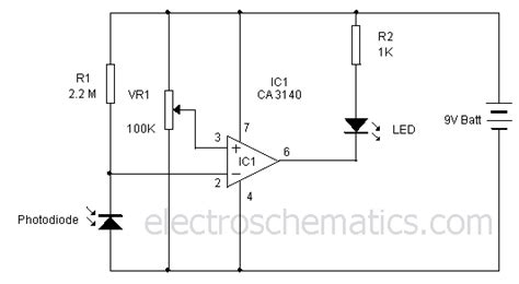
Light Intensity Measurement Circuit
A light intensity measurement circuit uses a photodiode or a phototransistor to measure the intensity of light and convert it into a voltage or current signal. The circuit typically includes an operational amplifier (op-amp) to amplify the small signal generated by the light-sensitive component.
          +5V
           |
           |
          +-+
          | |
          | | 100 kΩ
          | |
          +-+
           |
           |
     +-----+-----+
     |           |
    Photodiode   |
     |           |
     +-----+-----+
           |
           |
          +-+
          | |
          | | 1 MΩ
          | |
          +-+
           |
           |
          +-+
          | |
          | | Op-Amp
          | |
          +-+
           |
           |
          GND
The output voltage of the op-amp is proportional to the light intensity. This circuit can be used in applications like light meters, camera exposure meters, or ambient light sensors.

Frequently Asked Questions (FAQ)
-
Q: What is the difference between a photoresistor and a photodiode?
A: A photoresistor is a variable resistor whose resistance changes with light intensity, while a photodiode is a semiconductor device that generates a current proportional to the light intensity. Photoresistors are slower and less sensitive than photodiodes but are simpler to use and cost-effective. -
Q: Can I use a phototransistor instead of a photoresistor in the basic light detector circuit?
A: Yes, you can use a phototransistor in place of a photoresistor. However, you may need to adjust the resistor values to accommodate the different characteristics of the phototransistor. -
Q: How can I make the light detector circuit more sensitive?
A: To increase the sensitivity of the light detector circuit, you can use a more sensitive light-sensitive component like a photodiode or a phototransistor. Additionally, you can use an op-amp to amplify the signal generated by the light-sensitive component. -
Q: Can I use a light detector circuit to detect infrared light?
A: Yes, you can use a light detector circuit to detect infrared light by using an infrared-sensitive component like an infrared photodiode or an infrared phototransistor. These components are specifically designed to detect light in the infrared spectrum. -
Q: How do I choose the appropriate resistor values for my light detector circuit?
A: The resistor values in a light detector circuit depend on the characteristics of the light-sensitive component and the desired behavior of the circuit. Generally, you want to choose resistor values that allow a sufficient voltage drop across the light-sensitive component while ensuring that the current through the component is within its safe operating range. Experimenting with different resistor values and measuring the circuit’s response can help you find the optimal values for your specific application.
Conclusion
Light detector circuits are versatile and essential components in many electronic projects. By understanding the basics of light-sensitive components and how to use them in different circuit configurations, you can create a wide range of light-activated devices and sensors. Whether you are a beginner or an experienced electronics enthusiast, experimenting with light detector circuits can open up a world of possibilities for your projects. So grab your components, start building, and let your creativity shine!


Leave a Reply