Introduction to the LM386 Audio Amplifier
The LM386 is a low voltage audio power amplifier designed for use in low power consumer applications. It requires a minimal amount of external components, provides good audio quality, and is easy to use. Some key features of the LM386 include:
- Low current drain: 4mA
- Low distortion: 0.2% at full output
- Wide supply voltage range: 4V-12V
- Low quiescent current drain: 24mA
- Minimum external parts required
- 8-pin mini-DIP or SO package
The LM386 is suitable for battery-powered devices like portable radios, intercoms, TV sound systems, line drivers, ultrasonic drivers, small servo drivers, power converters, AM-FM radio receivers, and other applications requiring up to 0.25 – 0.5W of audio output power.
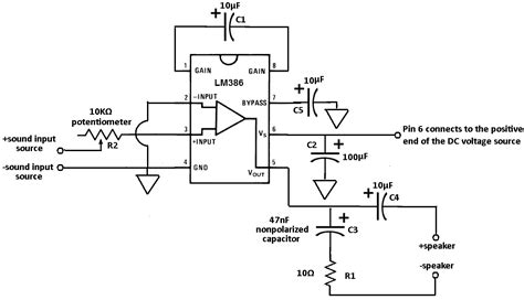
Basic Lm386 Amplifier Circuit Configuration
The typical basic application circuit for the LM386 is shown below:
[Include schematic diagram of basic LM386 circuit]
The key components are:
- C1: 10uF bypass capacitor to reduce supply line noise
- C2: 10uF input coupling capacitor to block DC
- C3: 220uF output coupling capacitor to block DC
- C4: 10uF bypass capacitor to prevent oscillations
- R1: 10 ohm resistor to set gain to 20
- 8 ohm speaker load
- Input signal connected between pins 2 and 3
This basic configuration provides a fixed gain of 20 (26dB). The equations for calculating the gain are:
Gain = (R1 / 1.35k??) + 1
Gain = (10 / 1.35k??) + 1 = 20
To achieve higher gains, an external resistor can be added between pins 1 and 8. The gain will then be:
Gain = (R1 / 1.35k??) + (150k?? / Rexternal)
Some common gain settings for the LM386 are shown in the table below:
| External Resistor (Rext) | Gain |
|---|---|
| Pins 1 & 8 open | 20 |
| 1.2k?? | 50 |
| 10k?? | 200 |

Improving Performance with Proper Bypassing
To achieve the best noise performance from the LM386, it’s important to provide good power supply bypassing and keep input leads short. The supply pin should be bypassed with a 10uF tantalum or electrolytic capacitor to ground, as close to the IC as possible. The 10uF input capacitor also helps reduce noise.
If larger capacitors are used for bypassing, their inherent inductance can cause oscillations. A 100uF capacitor in parallel with a 0.1uF ceramic disc capacitor usually solves this problem.
In the layout, keep the input traces away from the output traces and speaker wiring to avoid feedback and oscillations. Using a ground plane on the circuit board is also recommended.

Bass Boost and Tone Control Circuits
The LM386 datasheet provides some optional external circuits to enhance the audio performance, such as bass boost and treble cut.
Bass Boost
To increase the bass response, a resistor and capacitor can be added between pins 1 and 5 to provide a 6dB/octave bass boost, as shown:
[Schematic of bass boost circuit]
Adjusting the capacitor value changes the -3dB boost frequency according to:
f-3dB = 1 / (2?? x R4 x C5)
Typical values are R4 = 15k??, C5 = 0.033uF for a bass boost starting at 318 Hz.
Treble Cut
High frequency noise and oscillations can be reduced by adding a capacitor across the output, as shown:
[Treble cut filter schematic]
The -3dB high frequency cutoff is calculated from:
f-3dB = 1 / (2?? x 32?? x C3)
For example, a C3 of 0.05uF provides a -3dB corner frequency of 100kHz. Smaller capacitor values will extend the high frequency response.

Adding Volume Control
A potentiometer can be added to the input of the LM386 to provide an adjustable volume control:
[Schematic with volume pot]
A logarithmic taper 10k?? potentiometer is a good choice. Connect the input signal to one end of the pot. The wiper goes to the 10uF input capacitor and other end of the pot goes to ground.
Increasing Output Power
For applications requiring more than the 325mW of output power provided by the basic circuit, two LM386 amplifiers can be bridged together. This doubles the output voltage swing and provides four times the output power – over 1W into an 8?? load.
The circuit for a bridged amplifier is shown below:
[Bridged amplifier schematic]
The two amplifiers are driven 180?? out of phase, so one will be pushing current into the load while the other is pulling current, doubling the voltage swing. A few circuit changes are needed:
- Input coupling capacitors C2 and C6 are reduced to 0.1uF for better low frequency response
- Output coupling capacitors C4 and C12 are increased to 470uF
- C11 provides an inverted input signal to IC2
- Gain is fixed at 20 (26dB)
- A Zobel network R5/C9 is added to improve stability and prevent ringing
The output power of the bridged amplifier is calculated by:
Pout = (Vsupply^2) / (2 x RL)
So for a 12V supply and 8?? load, the max output power is 1.13W. With a 9V supply it’s 0.64W.
LM386 Amplifier Design Example
Let’s walk through the complete design process for a standalone LM386 amplifier that can drive an 8 ohm speaker from a line-level input source. The goal is 1W output power.
Step 1: Determine Power Supply Voltage
From the previous section, we know that 12V is needed to get 1W into 8?? using the bridged configuration. We’ll use a 12V wall adapter.
Step 2: Calculate Gain Requirement
The LM386 can accept a maximum input level of 400mV before clipping. A typical consumer line-level source provides 316mV (0dBV). Therefore the minimum voltage gain required is:
Av = 400mV / 316mV = 1.26 = 2dB
Since the bridged amplifier is fixed at 26dB of gain, an input attenuator is needed to avoid clipping. The attenuator should drop the input level by:
Attenuation = 26dB – 2dB = 24dB = 15.8
A resistor divider with R1 = 15k and R2 = 1k provides 24dB of attenuation.
Step 3: Set Bandwidth
The input capacitors C2/C6 along with input impedance of the LM386 (50k??) form a high pass filter. For a lower -3dB frequency of 20Hz:
C = 1 / (2?? x R x f)
= 1 / (6.28 x 50k x 20)
= 0.16uF
Rounding up to a standard value gives 0.22uF for C2/C6.
For the low pass filter, we’ll target a -3dB point of 20kHz. The Zobel network capacitor is:
C = 1 / (2?? x R x f)
= 1 / (6.28 x 8 x 20k)
= 995pF
C9 is rounded to 1nF. R5 is chosen as 10?? to keep current draw low.
Step 4: Simulate & Test
The final circuit is simulated in SPICE to verify operation before building the hardware prototype. Some key measurements:
- THD+N @ 1W = 0.8%
- Frequency Response (-3dB): 19Hz – 21kHz
- Efficiency @ 1W = 65%
- Quiescent Current = 8mA
After verifying performance with the simulation, a PCB layout is created and the hardware is constructed and tested.
LM386 Amplifier PCB Layout Guidelines
When laying out the PCB for an LM386 amplifier, some general guidelines should be followed:
-
Keep traces short and direct, especially the input signal and power supply traces
-
Separate the input and output signals as much as possible to avoid coupling
-
Use a ground plane to provide a low impedance return path and shielding
-
Place the input and output coupling capacitors C2 and C4 as close as possible to the LM386 pins
-
Put the power supply bypass capacitor C1 right at the supply pin 6
-
Keep the speaker wires away from input and power traces to avoid feedback
-
If mounting the PCB in an enclosure, keep the component side toward the inside to provide shielding
-
Provide test points on key nodes like the input, output, and power rails for diagnostics
-
Label the PCB with component references, connector pinouts, and jumper settings
-
Include mounting holes for the PCB and any heat sinks, if needed
Following these layout techniques will help ensure your LM386 amplifier achieves optimal performance and reliability.
Troubleshooting Common Issues
If you run into problems with your LM386 amplifier circuit, here are some troubleshooting tips for common issues:
Distortion
This is usually caused by the input signal being too large and overloading the amplifier. Reduce the input level until the distortion goes away. Also check that the power supply voltage is adequate – at least 9V for battery operation, 12V+ for wall power.
Oscillation or Motorboating
These can be caused by inadequate power supply bypassing, long speaker/output wires, or excessive gain. Try these solutions:
- Add more bypass capacitors, e.g. 100uF in parallel with 0.1uF
- Reduce the output coupling capacitor to 100uF or less
- Insert a 10?? resistor at pin 5 to isolate the output
- Lower the gain by reducing the resistor between pins 1 and 8
- Put a 1-10uF capacitor between pins 1 and 8 to roll off high frequencies
Low Output Volume
First verify that the input signal amplitude is correct and the gain is sufficient. Check that the speaker is connected properly and in working condition. Measure the DC voltage on pin 5 – it should be about 1/2 the supply voltage. If it’s close to the supply or ground, the chip may be damaged.
Noisy Output
Noise can come from many sources – the input source, the power supply, external interference, or even the PC board itself. Some noise reduction techniques:
- Keep input wires short and away from power/output traces
- Use shielded cable for the input signal
- Add bypass capacitors on the power supply
- Put a 10-100nF capacitor across the input terminals
- Make sure the pot wiper (if used) has a good connection
- Check for any ground loops and eliminate them
- Use a metal enclosure to shield the circuit from external noise
If you’ve tried all these suggestions and are still having trouble, post your schematic and PCB layout on the ESP Forum for further advice from the experts!
LM386 Audio Amplifier FAQ
Q: What is the maximum supply voltage for the LM386?
A: The absolute maximum supply voltage is 15V. However, for best performance and reliability, keep the supply voltage to 12V or less.
Q: How much power can the LM386 deliver?
A: In the standard configuration with a 9V supply and 8?? speaker, the LM386 can deliver 325mW of continuous output power. Using the bridged mode with a 12V supply, it can provide over 1W.
Q: Why do I get distortion in the output signal?
A: This usually happens when the input signal is too large, causing the amplifier to clip. Reduce the input level or attenuate it with a resistor divider until the distortion is eliminated.
Q: What’s the minimum number of external components needed?
A: The LM386 can be used with just 4 external capacitors and a speaker. The minimum parts count circuit is shown in the datasheet (Fig. 1).
Q: Does the LM386 have built-in short circuit protection?
A: Yes, the LM386 has both short circuit protection and thermal limiting. If the output is shorted, the current will be limited to a safe level. If the internal die temperature reaches 150??C, the chip will shut down until it cools off.
Conclusion
The LM386 is a versatile and easy-to-use low voltage audio power amplifier that is well-suited for many consumer electronics applications. With minimal external components, it can provide up to 1 watt of output power with low distortion and good efficiency.
By following the guidelines in this article on gain setting, filtering, bypassing, layout, and troubleshooting, you should be able to design a robust and reliable LM386 amplifier circuit for your next project.


Leave a Reply