What is FR4?
FR4 is a grade designation assigned to glass-reinforced epoxy laminate sheets, tubes, and rods. It is one of the most common materials used as an electrical insulator in the production of printed circuit boards (PCBs). The FR in FR4 stands for flame resistant, indicating that the material meets certain flammability standards.
Some key properties of FR4 include:
- Good electrical insulation properties
- Good mechanical strength
- Relatively inexpensive compared to other circuit board materials
- Can be etched easily to create trace patterns
FR4 is created by impregnating woven fiberglass mat with an epoxy resin binder. This material is then cured under heat and pressure to form a solid laminate with the fiberglass cloth encapsulated within the epoxy. Multiple layers of copper and FR4 can be laminated together to create a PCB substrate.
What is a PCB Stiffener?
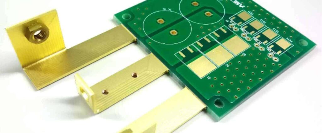
A PCB stiffener is a mechanical part that is mounted to a printed circuit board to strengthen and support it. Stiffeners help prevent warping or flexing of the PCB, which could cause cracking or separation of traces. They are especially useful for large circuit boards or boards that need to withstand vibration and shock loads.
PCB stiffeners are typically made from rigid materials like aluminum, steel, FR4, or plastic. FR4 is a common choice for economic and fabrication reasons. The stiffener is mounted parallel to the surface of the PCB using standoffs, adhesive, or press-fit connections. This helps transfer mechanical stresses from the board to the stiffener.
Some key benefits provided by PCB stiffeners include:
- Reduce PCB warpage and bowing
- Improve resistance to shock and vibration forces
- Prevent damage to PCB components and solder joints
- Allow use of thinner, more flexible PCB materials
- Can act as a heat sink to dissipate heat from components
When are FR4 Stiffeners Needed?
Here are some situations where using an FR4 stiffener would be beneficial for a PCB design:
Large or thin PCBs
Larger PCBs are more prone to flexing and warping stresses. Thinner boards are particularly susceptible. Mounting a stiffener helps reinforce these boards.
High component density
PCBs with many tall components placed near the board edge need stiffening to prevent localized bowing. This helps avoid cracking joints under the components.
PCBs subject to shock/vibration
Equipment like telecom systems, industrial controls, and vehicle electronics experience high vibration forces. Stiffeners help strengthen PCBs in these applications.
PCBs with large/heavy components
Power components, transformers, and heat sinks can cause mechanical stresses. Stiffeners help support the weight and forces from these components.
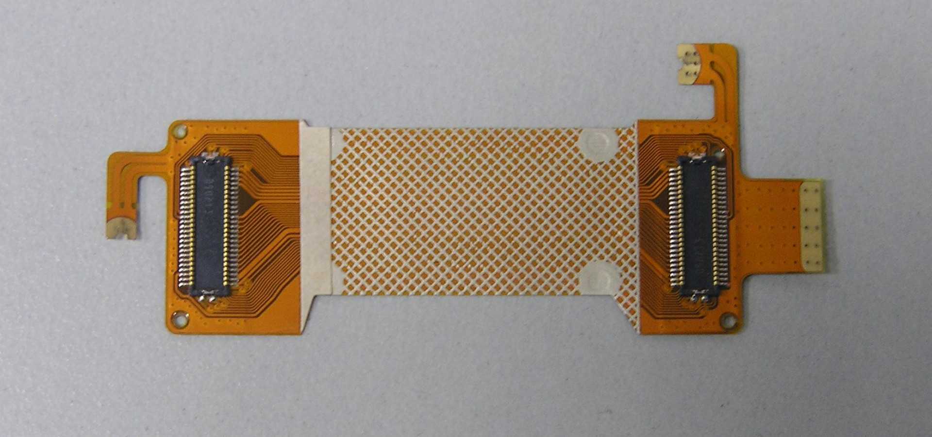
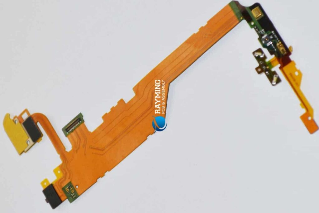
Flexible/multi-layer PCBs
Flex PCBs and multilayer boards with thin dielectric layers are prone to flexing. Stiffeners give mechanical support.
PCBs used in high temperature environments
Stiffeners can act as heat sinks and help dissipate heat from boards used in hot environments.
How to Design FR4 Stiffeners
Here are some best practices to follow when designing FR4 stiffeners:
- Match coefficient of thermal expansion (CTE) – Use FR4 material that closely matches the CTE of the PCB laminate. This reduces stresses from temperature changes.
- Model the stiffener in PCB layout – Include the stiffener footprint in the PCB layout. This ensures components and traces are positioned appropriately.
- Align stiffener parallel to board surface – Mount the stiffener parallel with the plane of the PCB. This provides the best strengthening support.
- Use corner support – Extend the stiffener to the edges or corners of the PCB to get better strengthening.
- Pay attention to standoff height – The standoff height impacts stiffener performance. Lower standoffs increase support but may cause grounding issues.
- Mind internal cutouts and holes – Allow space for components that protrude through the stiffener. Holes reduce performance so use judiciously.
- Include lead-in chamfers – Chamfering the edges that go into the PCB allows for easier assembly.
- Select durable plating – Use nickel, gold, or tin plating to protect stiffener copper from oxidation and improve solderability.
Stiffener Analysis and Simulation
To ensure a stiffener design provides enough mechanical support, engineers will often perform finite element analysis (FEA) simulations. This involves modeling the PCB board and stiffener together, then applying representative forces, constraints, and boundary conditions. The simulation predicts stresses and displacements that estimate real-world behavior.
Analysis can examine different placement configurations, stiffener thickness, material properties, and other parameters to optimize the design. This helps avoid costly redesigns if issues emerge after PCB fabrication.
Some types of analyses performed include:
- Static stress – Apply steady-state forces like flexing and compression to see maximum stresses.
- Vibration – Simulate vibration modes and frequencies experienced during use. Verifies stiffener prevents harmful resonances.
- Shock – Model short duration shock loads and impacts the PCB may experience.
- Thermal – Check thermally induced stresses from temperature cycling and gradients.
- Drop impact – Replicate impacts from free-fall drops that could occur during transportation or installation.
Manufacturing and Installation
FR4 stiffeners can be fabricated using standard PCB manufacturing techniques like milling, drilling, and etching. This allows them to be cost-effectively mass produced. Stiffeners require additional fabrication steps than normal PCBs:
Milling – A CNC milling machine cuts the stiffener outline from an FR4 panel. Interior cutouts are also milled.
Drilling – Mounting holes are precision drilled for attaching standoffs. Somestiffeners may also require holes for component clearance.
Plating – The exposed copper is plated to protect from oxidation and improve solderability. Electroless nickel/immersion gold is commonly used.
Silkscreen – Reference designators, fiducials, and other markings are printed to aid assembly.
To install the stiffener:
- Standoffs are fixed to the PCB using solder or adhesive at defined locations.
- The stiffener is placed over the standoffs and attached using screws or press-fitting.
- Optional tamper-proof screws can deter unauthorized access to the PCB interior.
Cost Considerations
Adding stiffeners increases the total cost of a PCB design. Some cost factors include:
- Additional FR4 material required
- Increased PCB panel size
- Extra fabrication processing steps
- Mounting hardware (standoffs, screws, adhesive)
- More complex assembly procedure
However, the stiffener cost is typically far outweighed by the benefits. It prevents failures caused by flexing that would be very expensive to remediate. Stiffening also allows the use of cheaper, thinner PCB material.
Done judiciously, PCB stiffening delivers excellent return on investment and avoids costly field failures. The small incremental cost during design is paid back many times over in improved product quality and reliability.
Summary
- FR4 stiffeners reinforce PCBs and prevent failures caused by flexing, vibration, and shock stresses.
- They are commonly used on large, thin, or high density boards where flexure could damage traces and joints.
- Careful design, simulation, and analysis ensures the stiffener provides optimal mechanical support.
- FR4 material can be cost-effectively fabricated using standard PCB manufacturing techniques.
- Intelligently incorporating stiffening features enhances the reliability and robustness of PCB designs.
Frequently Asked Questions
What are some alternatives to FR4 for PCB stiffeners?
Some other common materials for PCB stiffeners besides FR4 include aluminum, carbon fiber, polycarbonate, stainless steel, and rigid composite boards like FR408. The optimal material depends on cost, CTE matching, strength, and other requirements.
What is the typical thickness for an FR4 stiffener?
A commonly used thickness range for FR4 stiffeners is 0.062” – 0.125” (1.6 – 3.2 mm). Thicker stiffeners provide more rigidity but add more mass. Multiple thin stiffeners can be used instead of one thick one for weight savings.
Can stiffeners be used to aid thermal dissipation?
Yes, metal stiffeners made of aluminum or copper can be used as heat spreaders and sinks. They wick heat from hot components and spread it over a larger surface area. Thermal interface materials are used to improve heat conduction into the stiffener.
How are stiffeners analyzed for vibration environments?
FEA modal analysis is used to find natural frequencies of the PCB with stiffener. These are compared to vibration spectra for the operating environments. Stiffener design is adjusted to avoid resonances at key environmental frequencies.
What are some installation mistakes to avoid with stiffeners?
Use all mounting standoffs and screws to evenly distribute force. Make sure stiffener is seated flush to avoid rocking. Watch for shorts between stiffener and components/traces. Avoid overtightening screws. Apply adhesive or epoxy evenly under stiffener.


Leave a Reply