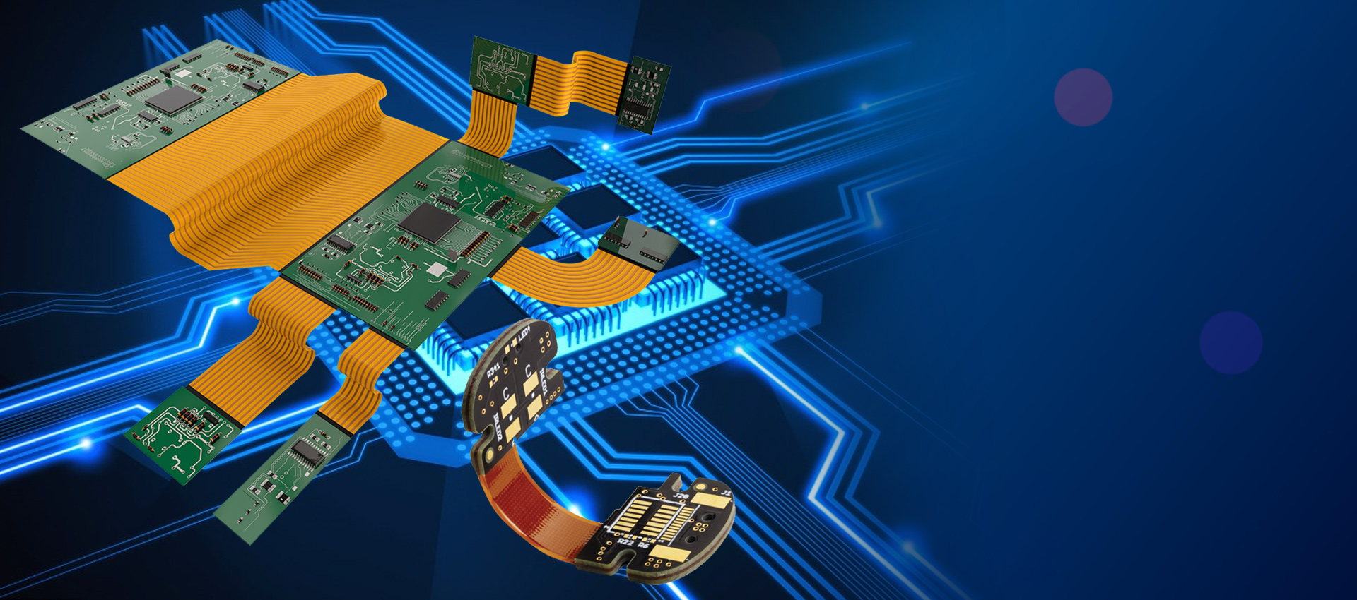
FPC PCB (Flexible Printed Circuit Board) is a type of printed circuit board that is made of flexible and bendable material. Unlike traditional rigid PCBs, FPCs can be repeatedly flexed and bent without damage during use. FPCs are extremely thin, lightweight and ideal for applications where flexibility, space savings, and weight reduction are critical design considerations.
Definition of FPC
FPC gets its name from the acronym “Flexible Printed Circuit”. As the name suggests, it is a printed circuit board made of flexible insulating substrate material such as polyimide or polyethylene terephthalate (PET). The electrical wiring paths known as conductive traces are etched or printed on the flex circuit using copper or other conductive materials. Components can be soldered directly onto the FPC conductors to form a complete electronic circuit assembly.
Key Features of FPC
- Extremely thin – as low as 25um
- Lightweight and flexible
- Can be bent repeatedly without damage
- Saves space and weight in designs
- Simplifies complex interconnects
- Enables movement/flexing of circuits
- Withstands vibration and flexing forces
- Low cost compared to rigid-flex PCBs
Applications and Use Cases of FPC
FPCs are widely used in consumer electronics, automotive, industrial, medical, military and aerospace applications where flexibility, space savings and durability are important.
Consumer Electronics
FPCs are ubiquitous inside smartphones, laptops, wearables, VR headsets, game consoles, TVs and other portable consumer electronics:
- Connecting mainboards to displays
- Interconnects between rigid PCB assemblies
- Flex cable connections inside hinged devices
Automotive
FPCs are used under the hood for engine control units, sensors, LED lighting, switches, touch sensors and other auto electronics:
- Flexible cabling for steering wheel controls
- Around moving parts and hinges
- Saving space in tight compartments
Industrial
FPCs enable movement and flexing in machinery and instrumentation:
- Moving robot joints and arms
- Printheads in large industrial printers
- Inside test chambers and equipment
- Flex-to-board connectors on devices
Medical
FPCs provide flexibility for monitors, sensors and devices used on patients:
- EKG/ECG pads and sensors
- Endoscopes, catheters and implants
- Wearable health monitors
- Saving space in portable equipment
Military/Aerospace
Ruggedized FPCs meet durability needs in demanding environments:
- Missile guidance systems
- Avionics and flight controls
- Space satellite mechanisms
- Radars and defense electronics
Others
Many other specialty uses benefit from FPC properties:
- POS terminals, handheld scanners
- Solar panels
- LED signage and lighting
- Motor/motion control
- Sensors and instrumentation
Benefits of Using FPC
Compared to rigid boards, FPCs provide unique advantages:
- Flexible – Can be dynamically flexed, bent, folded
- Thin – Extremely low profile, as thin as 25um
- Lightweight – Up to 75% less weight than rigid PCBs
- Durable – Withstands flexing, vibration, shocks
- Space saving – Fits into tight spaces, complex shapes
- Simplifies assembly – Fewer connectors needed
- Lower cost – Cheaper than rigid-flex PCBs
- Customizable – Can be cut, formed, shaped as needed
FPC Design Considerations
Designing with FPC requires some special considerations:
Flexible Substrate Materials
The flexible dielectric material must withstand repeated bending without damage. Common substrates are:
- Polyimide – Most popular, can withstand millions of flex cycles
- Polyester (PET) – More economical option
- PEN, PEI, PEEK – High temperature substrates
Minimum bend radius – The substrate and copper traces have a limit on how tight they can be bent without risk of damage. Typical minimum bend radius is about 10x the FPC thickness.
Conductive Traces
The copper traces must be very thin to retain flexibility. Common thicknesses are:
- 1/2 oz (18 um) copper
- 1 oz (35 um) copper
- 2 oz (70 um) copper
Narrow trace widths and spaces down to 100 um (4 mil) are typical.
Stiffeners and Reinforcement
Some sections may need stiffeners or covers to prevent overflexing damage. Common options:
- Adhesive covers – PET, polyimide
- Silkscreen layer – Epoxy or acrylic ink
- Copper stiffeners – Additional copper layers
Connectors and Terminations
Connections from FPC to other boards often use zero insertion force (ZIF) or other special connectors. Common options:
- ZIF/FFC connectors – Low insertion force
- Anisotropic conductive film – No solder required
- Crimping – presses conductor into insulation
- Soldering – reflow compatible flex circuits
Component Mounting
Components can be soldered to FPCs, but may require adhesives or fasteners to strengthen the bond:
- SMT components – reflow solderable
- Through-hole parts – wave or selective soldering
- Mechanical attachments – screws, clamps, adhesive
The flexing action subjects solder joints to cyclic fatigue stresses which can cause intermittent connections. Proper design is needed to avoid flex crack failures.
FPC Manufacturing Processes
FPC fabrication involves printing the circuit traces onto the flexible substrates using photolithography and etching processes adapted from rigid PCB manufacturing.
Base Material
The process starts with bare polyimide or other flex circuit substrate in roll or sheet form with adhesive backing. The material is typically 25um to 100um thick. The copper foil is usually 1/2 oz or 1 oz thickness.
Imaging
A photoresist coating is applied over the copper layer. Next, the circuit patterns are imaged using exposes and phototools similar to rigid PCB fabrication.
Etching
The unexposed photoresist is developed away, exposing the copper to be etched. The board is etched to remove unwanted copper, leaving only the desired circuit traces.
Stripping and Finishing
The remaining photoresist is stripped away. The FPC then goes through various plating and finishing steps such as:
- Oxidation treatment – for adhesion
- Tin lead plating – etch resistance
- Gold plating – for contact points
- Carbon ink – conductive glue tracks
- Coverlay application – for insulation
Solder Mask
A solder mask coating is applied over the FPC to cover copper traces and prevent solder bridges. Openings are created over solderable areas.
Singulation
Individual FPC sections are cut or routed from the panel. Registration holes aid in precision cutting.
Assembly
Components are then soldered onto the FPC using reflow ovens or other attachment methods. Connectors are added, and the flex assembly is tested.
FPC vs Rigid-Flex PCBs
FPC is one type of flexible PCB, but another option is rigid-flex PCBs. Here is a comparison:
| Parameter | FPC | Rigid-Flex PCB |
|---|---|---|
| Construction | Only flexible PCB material | Multi-layer combo of rigid and flex |
| Flexibility | Entire board is flexible | Only flex section bends |
| Layer Count | 1 or 2 layer typical | >4 layers common |
| Thickness | 25 um – 100 um | > 200um typical |
| Cost | Lower | Much higher |
| Design | Limited by flexibility | Rigid areas allow complex design |
| Applications | Mostly dynamic flex needs | Combines rigid and flex |
Rigid-flex PCBs provide more layers and design complexity, but are more expensive. FPCs offer the simplest and lowest cost flexible circuit solution.
FPC Design Software
FPC layout and routing requires specialized CAD tools to handle the unique needs of flexible circuits. Some options:
- Altium Designer – Industry standard PCB tool with flex and rigid-flex capabilities
- Mentor Xpedition – Enterprise engineering suite with flex PCB options
- Cadence Allegro – Full featured PCB and IC packaging design solution
- Zuken CR-8000 – Dedicated flex and rigid-flex layout tool
- Sunstone Circuits PCB Artist – Free FPC design tool
These tools allow interactive routing of flex circuits, checking of bend radii, modeling of flex regions, analysis of stresses, and other critical functions.
Leading FPC Manufacturers
Some of the top companies producing FPC include:
- Multi-Circuit Boards
- Flexible Circuit Technologies (FCT)
- All Flex
- Minco
- Sumitomo Electric Printed Circuits
- Flexible Printed Circuits (FPC) Limited
- Flexible Circuit Technologies
- Compass Circuits
Both large electronics manufacturers and specialized flex circuit fabricators offer FPC services. Partnering with an experienced flex PCB supplier is key to ensuring manufacturability and reliability.
FPC Connector Types
There are various connector styles used to connect FPC to other boards and components:
| Connector | Description |
|---|---|
| FFC/FPC | Zero insertion force flex connectors |
| FFV | Vertical FFC connectors |
| HDF/HDP | High-density connectors for small pitch FFC |
| FFTB | Through board flex connectors |
| AFCA | Anisotropic conductive adhesives |
| Compression | Crimp-style press fit connectors |
FPC Connector Companies
Major manufacturers providing FPC connectors include:
- Molex
- TE Connectivity (AMP)
- Hirose Electric
- JAE Electronics
- JST
- Samtec
- Omron
- Amphenol FCI
- Stocko Contact
FPC vs Traditional Wiring Harnesses
Traditionally, electrical wiring interconnects were done using discrete insulated wires bundled into cable harnesses. FPC offers benefits over old-fashioned cabling:
| Parameter | Traditional Wiring Harness | FPC |
|---|---|---|
| Construction | Discrete insulated wires | Printed circuit traces on flex substrate |
| Flexibility | Wires can flex individually | Entire assembly flexes together |
| Weight | Heavy due to multiple wires | Up to 75% less weight |
| Size | Bulky with wire bundles | Extremely thin profile |
| Complexity | Labor intensive cabling | Simplifies interconnects |
| Durability | Prone to failure at wire exits | Withstands fatigue and flexing |
| EMI | No shielding | Can incorporate EMI shielding |
| Waterproofing | Individual wires resist moisture | Can coat entire assembly |
| Cost | Higher labor | Lower cost |
FPC provides substantial savings in weight, space, assembly time, durability, and overall life cycle costs compared to old-fashioned cabling approaches. The transition from hand wiring to flex circuits was a major advance in electronic packaging and interconnection.
FPC Applications and Examples
Here are some examples of innovative FPC implementations:
- Consumer Tech – Flexible circuits connect LCD/OLED displays to PCBs in smartphones, TVs, laptops. Apple Watch band integrates FPC with sensors.
- Automotive – FPCs link control buttons on steering wheel to electronics. Also used in blind spot detection, video mirrors, sensors.
- Medical – Flexible circuits integrated into patient monitoring patches, glucose sensors, disposable diagnostics.
- Industrial – FPCs connect moving printheads on wide format printers. Also used in robotics arms.
- Military – Ruggedized flex circuits operate antennas and radar systems in extreme environments. Used in missiles and soldier systems.
- Aerospace – Flexible circuit boards on joints of robotic arms on Mars rovers and space stations. Also used in satellites and UAVs.
Some recent uses of FPC include Apple’s dynamic island, VR headsets, flexible displays, advanced driver assistance systems (ADAS), and foldable smartphones. The unique properties of FPC enable many leading-edge electrical and mechanical systems across industries.
FPC Design and Specification Checklist
Here is a summary checklist of key considerations when specifying and implementing an FPC design:
- Define circuit performance requirements
- Select substrate material – polyimide, PET, etc
- Determine conductor construction – 1/2 oz, 1 oz copper etc
- Specify minimum trace width/spacing based on current
- Calculate minimum bend radius based on flex life cycles
- Add stiffeners or reinforcement in high flex areas
- Select connectors for interfacing with other boards
- Determine if components require mechanical attachment
- Specify protective coverlay and solder mask
- Outline board regions that will flex dynamically
- Verify DFM/DFA rules with manufacturer
- Prototype and physically test flexing performance
- Analyze stresses using FEA tools if needed
Careful planning and review of FPC design requirements will ensure optimal functionality and reliability. Partnering with an experienced manufacturer is highly recommended.
FPC Design Guide and Additional Resources
Here are some excellent resources for further learning about FPC design:
Flex Circuit Design Guide from Sunstone Circuits covers all key aspects of specifying and designing FPCBs. Highly recommended overview guide.
Flexible Circuit Technologies FPC Guides – Design aid, materials guide and other resources from flex circuit manufacturer FCT.
All Flex Flexible Circuits Design Guide – Reference covering the design process, principles, and manufacturing.
Minco Flex Circuit Design Guide – Another great design and manufacturing resource from Minco.
IEC 61340-5-1 – Standard for flexible printed board design, handling and assembly.
IPC-2223 – Flexible printed wiring design standard from IPC.
For further questions please ask the experts at your flex circuit partner or PCB manufacturer early in the design process. Their guidance can prevent issues and ensure reliable performance of your flexible circuit board.


Leave a Reply