Introduction to Flex-Rigid PCBs
Flexible Rigid PCBs, also known as Flex-Rigid PCBs or simply Rigid-Flex PCBs, are a unique combination of rigid and flexible printed circuit board technologies. This innovative design allows for the integration of both rigid and flexible substrates into a single circuit board, offering numerous advantages over traditional rigid PCBs or flexible PCBs alone.
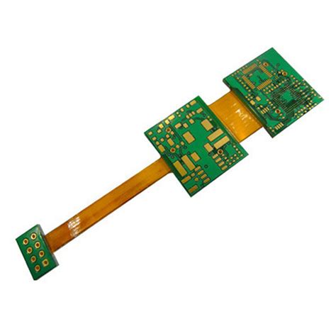
Flex-Rigid PCBs consist of multiple layers of rigid and flexible substrates that are laminated together to form a single, cohesive unit. The rigid portions of the board provide structural support and house the majority of the components, while the flexible portions allow for bending, folding, and twisting of the board to fit into tight spaces or conform to unique shapes.
Advantages of Flex-Rigid PCBs
- Space Savings: Flex-Rigid PCBs allow for more compact and efficient packaging of electronic components, reducing the overall size and weight of the device.
- Improved Reliability: By eliminating the need for connectors and cables between rigid boards, Flex-Rigid PCBs minimize potential points of failure and enhance overall system reliability.
- Enhanced Signal Integrity: The continuous copper traces across rigid and flexible sections reduce signal loss and interference, resulting in improved signal integrity.
- Design Flexibility: Flex-Rigid PCBs offer greater design flexibility, enabling engineers to create complex, three-dimensional structures that would be impossible with traditional rigid PCBs.
- Cost Reduction: Although the initial cost of Flex-Rigid PCBs may be higher than traditional PCBs, the overall system cost can be reduced by eliminating connectors, cables, and the associated assembly processes.
Flex-Rigid PCB Assembly Challenges
Despite the numerous benefits of Flex-Rigid PCBs, their assembly process presents unique challenges that must be addressed to ensure reliability and performance.
1. Material Selection
Choosing the right materials for Flex-Rigid PCBs is crucial to ensure the desired flexibility, durability, and electrical performance. The most common flexible substrates used in Flex-Rigid PCBs are polyimide (PI) and polyester (PET). PI offers excellent heat resistance, dimensional stability, and electrical properties, making it the preferred choice for high-reliability applications. PET, on the other hand, is more cost-effective and suitable for less demanding applications.
The rigid portions of the board typically use standard FR-4 material, which provides good mechanical strength and electrical insulation properties.
2. Lamination Process
The lamination process for Flex-Rigid PCBs is more complex than that of standard rigid PCBs. The flexible and rigid substrates must be laminated together under precise temperature, pressure, and time controls to ensure proper bonding and prevent delamination.
One of the key challenges in the lamination process is managing the different thermal expansion rates of the flexible and rigid materials. This can lead to warping or curling of the board if not properly controlled. To mitigate this issue, specialized lamination techniques, such as sequential lamination or the use of low-flow prepregs, can be employed.
3. Component Placement and Soldering
Component placement and soldering on Flex-Rigid PCBs require special considerations to account for the unique properties of the flexible portions of the board.
For surface mount components, it is essential to use a flexible solder mask that can withstand the bending and flexing of the board without cracking or peeling. Additionally, the component placement should be optimized to minimize stress on the solder joints during flexing.
Through-hole components pose a greater challenge, as the holes in the flexible portions of the board can weaken the substrate and lead to fatigue failures. To address this issue, techniques such as selective reinforcement or the use of filled via technology can be employed to strengthen the hole area and improve reliability.
4. Bending and Folding
One of the primary advantages of Flex-Rigid PCBs is their ability to bend and fold to fit into tight spaces or conform to unique shapes. However, this flexibility also presents challenges in the assembly process.
To ensure reliable bending and folding of the board, it is crucial to design the flexible portions with the appropriate bend radius and number of layers. The bend radius should be large enough to prevent excessive stress on the copper traces and substrate, while the number of layers should be minimized to maintain flexibility.
In addition, the placement of components and traces should be optimized to avoid the bending zones whenever possible. If components must be placed in the bending area, they should be selected and oriented to minimize stress during flexing.
5. Testing and Inspection
Testing and inspection of Flex-Rigid PCBs are critical to ensure the quality and reliability of the final assembly. However, the unique properties of these boards can make traditional testing methods less effective.
For example, standard bed-of-nails testing may not be suitable for the flexible portions of the board, as the pressure from the test probes can damage the substrate or cause false failures. Instead, alternative testing methods, such as flying probe testing or boundary scan testing, may be used to assess the integrity of the assembly.
Visual inspection of Flex-Rigid PCBs can also be challenging, particularly in the flexible areas where components and traces may be hidden from view. Automated optical inspection (AOI) systems with specialized algorithms and lighting techniques can be employed to detect defects and ensure the quality of the assembly.

Best Practices for Flex-Rigid PCB Assembly
To overcome the challenges associated with Flex-Rigid PCB assembly and ensure a reliable and efficient process, consider the following best practices:
- Collaborate closely with your PCB fabricator and assembly partner early in the design process to ensure that your design is optimized for manufacturability and reliability.
- Use appropriate materials for the flexible and rigid portions of the board, considering factors such as flexibility, durability, and electrical performance.
- Employ specialized lamination techniques, such as sequential lamination or the use of low-flow prepregs, to manage the different thermal expansion rates of the flexible and rigid materials.
- Optimize component placement and soldering techniques to minimize stress on the solder joints during flexing, and use flexible solder masks for surface mount components.
- Design the flexible portions of the board with the appropriate bend radius and number of layers to ensure reliable bending and folding.
- Utilize alternative testing methods, such as flying probe testing or boundary scan testing, to assess the integrity of the assembly without damaging the flexible substrate.
- Implement automated optical inspection (AOI) systems with specialized algorithms and lighting techniques to detect defects and ensure the quality of the assembly.
By following these best practices and working closely with experienced Flex-Rigid PCB fabrication and assembly partners, you can overcome the challenges associated with these unique boards and create reliable, high-performance assemblies that meet your specific application requirements.

Flex-Rigid PCB Applications
Flex-Rigid PCBs find applications in a wide range of industries and products where space savings, reliability, and design flexibility are critical. Some common applications include:
- Aerospace and Defense: Flex-Rigid PCBs are used in avionics, satellites, and military equipment where weight reduction, reliability, and the ability to withstand harsh environments are essential.
- Medical Devices: Flex-Rigid PCBs are employed in medical devices such as wearable monitors, implantable devices, and diagnostic equipment, where compact packaging and reliability are paramount.
- Automotive Electronics: As vehicles become more complex and electronics-laden, Flex-Rigid PCBs are used in applications such as dashboard displays, engine control units, and advanced driver assistance systems (ADAS).
- Consumer Electronics: Flex-Rigid PCBs are found in smartphones, tablets, smartwatches, and other portable devices where space is at a premium and reliability is critical.
- Industrial Automation: Flex-Rigid PCBs are used in robotics, machine vision systems, and other industrial automation applications where compact packaging, reliability, and design flexibility are essential.
As technology continues to advance and the demand for smaller, more reliable electronic devices grows, the use of Flex-Rigid PCBs is expected to increase across a wide range of industries and applications.

Frequently Asked Questions (FAQ)
- What is the difference between a Flex-Rigid PCB and a standard flexible PCB?
-
A Flex-Rigid PCB combines both rigid and flexible substrates into a single circuit board, allowing for the integration of components on the rigid portions while maintaining the ability to bend and fold in the flexible areas. A standard flexible PCB, on the other hand, consists entirely of flexible substrate material and does not have any rigid portions.
-
What are the main advantages of using Flex-Rigid PCBs?
-
The main advantages of using Flex-Rigid PCBs include space savings, improved reliability, enhanced signal integrity, design flexibility, and potential cost reduction. These benefits stem from the ability to eliminate connectors and cables, reduce the overall size and weight of the device, and create complex, three-dimensional structures that would be impossible with traditional rigid PCBs.
-
What materials are commonly used in Flex-Rigid PCBs?
-
The most common flexible substrates used in Flex-Rigid PCBs are polyimide (PI) and polyester (PET). PI is preferred for high-reliability applications due to its excellent heat resistance, dimensional stability, and electrical properties. PET is more cost-effective and suitable for less demanding applications. The rigid portions of the board typically use standard FR-4 material.
-
How does the lamination process for Flex-Rigid PCBs differ from standard rigid PCBs?
-
The lamination process for Flex-Rigid PCBs is more complex than that of standard rigid PCBs. The flexible and rigid substrates must be laminated together under precise temperature, pressure, and time controls to ensure proper bonding and prevent delamination. Specialized lamination techniques, such as sequential lamination or the use of low-flow prepregs, may be employed to manage the different thermal expansion rates of the materials.
-
What are some of the key challenges in assembling Flex-Rigid PCBs?
- Some of the key challenges in assembling Flex-Rigid PCBs include material selection, lamination process control, component placement and soldering, bending and folding, and testing and inspection. These challenges arise from the unique properties of the flexible portions of the board and require specialized techniques and considerations to ensure reliability and performance.
Conclusion
Flex-Rigid PCBs offer a unique combination of benefits, including space savings, improved reliability, enhanced signal integrity, design flexibility, and potential cost reduction. By integrating both rigid and flexible substrates into a single circuit board, Flex-Rigid PCBs enable the creation of complex, three-dimensional structures that would be impossible with traditional rigid PCBs or flexible PCBs alone.
However, the assembly of Flex-Rigid PCBs presents unique challenges that must be addressed to ensure reliability and performance. These challenges include material selection, lamination process control, component placement and soldering, bending and folding, and testing and inspection.
To overcome these challenges and ensure a successful Flex-Rigid PCB assembly, it is essential to collaborate closely with experienced fabrication and assembly partners, employ best practices and specialized techniques, and carefully consider the unique properties and requirements of these innovative circuit boards.
By understanding the advantages, challenges, and best practices associated with Flex-Rigid PCBs, designers and engineers can harness the full potential of this technology to create reliable, high-performance assemblies that meet the evolving needs of a wide range of industries and applications.


Leave a Reply