Printed circuit boards (PCBs) are essential components in nearly all modern electronics. PCBs provide the foundation onto which microchips, capacitors, resistors and other components are mounted. They contain the conductive pathways or traces that electrically connect all the components.
PCBs come in two main types – flexible PCBs and rigid PCBs. Each has its own set of advantages and ideal applications. This article provides a detailed comparison of flexible and rigid PCBs to help you determine which is better for your project.
What are Flexible PCBs?
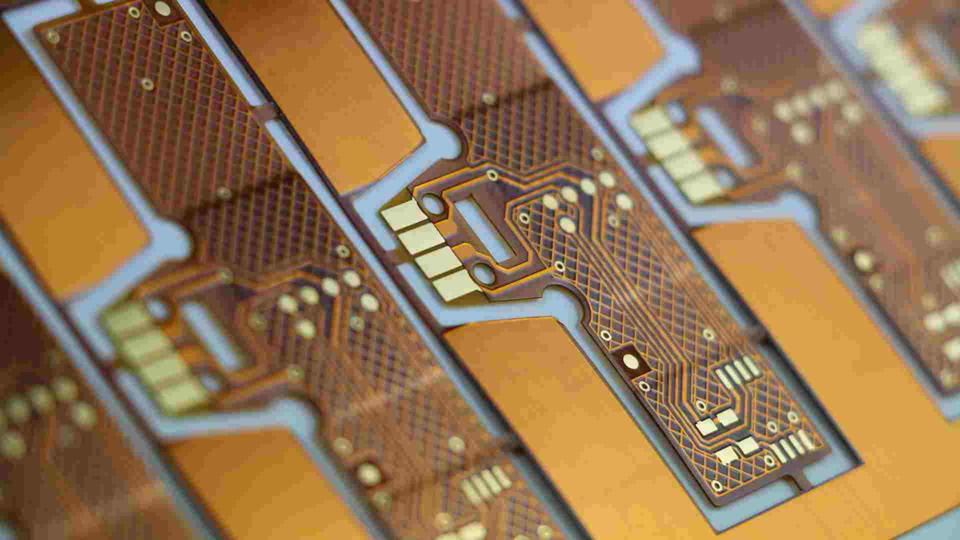
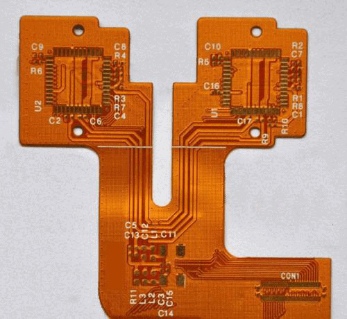
A flexible printed circuit board (flex PCB or flex circuit) is made of a thin insulating flexible plastic substrate onto which conductive traces are printed or bonded. The most commonly used flexible substrate materials are polyimide and polyester.
Flex PCBs can bend, twist and flex without damage during use or installation. This makes them perfect for applications where wiring harnesses would be too bulky or rigid PCBs won’t fit.
Common applications of flexible PCBs include:
- Wearable devices – watches, fitness bands
- Medical devices
- Robotics and drones
- Consumer electronics – cameras, cell phones
- Automotive electronics
Flex circuits allow convenient interconnections between separate rigid PCBs. They are often used as interconnects between rigid PCBs in products like notebook computers and mobile devices.
Benefits of Flex PCBs
Here are some of the main benefits of using flexible PCBs:
- Lightweight and thin – Flex PCBs have a thickness typically between 25-100 microns. The thin polyimide substrate makes them extremely lightweight.
- Highly flexible – Can be flexed, twisted and bent repeatedly without damage. Flexible PCBs are ideal for fitting into tight, cramped spaces.
- Durable – Polyimide substrate and copper traces stand up well to bending and flexing stresses. Flex circuits have a long service life.
- Excellent thermal shock resistance – Withstands high temperature fluctuations without damage.
- Ideal for complex interconnects – Flex circuits can accommodate complex wiring patterns between PCBs and components.
- Soft and foldable – Allows conformability to curved surfaces like cylinders or spheres.
- No soldering required – Components attach via conductive epoxy, heat seal connections or mechanical clamping.
- Reduces wiring errors – Integrated flex interconnects minimize loose wiring that can introduce errors.
Limitations of Flex PCBs
Flex PCBs also come with the following limitations:
- More expensive – Flex PCB fabrication typically costs more than rigid PCBs, due to specialized materials and processes.
- Lower circuit densities – Trace widths and spaces are larger. Flex PCBs cannot accommodate fine-pitch components.
- Single-sided circuits only – Traces can only be patterned on one side of the substrate. Double-sided flex PCBs are rare.
- Limited component mounting – Only smaller, lighter components can be mounted directly on the thin flex circuits.
- Prone to wear and tear – Continuous flexing in one area can cause the conductive traces to eventually crack and break.
- Repairs difficult – It’s challenging to troubleshoot and fix faults on flexible circuits.
What are Rigid PCBs?
Rigid printed circuit boards are made from sheets of rigid insulating substrate material that provide mechanical support. Common rigid PCB substrate materials include FR-4 glass epoxy and composites like FR-1 paper epoxy.
The rigid board retains its shape during and after fabrication. This allows mounting of heavier electronic components like ICs, connectors, capacitors, etc. Rigid PCBs contain conductive copper tracks to electrically interconnect the mounted components.
Typical applications of rigid PCBs include:
- Computers and servers
- Telecommunications infrastructure
- Industrial electronics and control systems
- Automotive electronics
- Consumer electronics – TVs, stereos, etc.
Rigid PCBs make up the majority of PCB production today. They offer greater circuit complexity and component densities than possible with flex PCBs.
Benefits of Rigid PCBs
Here are some of the advantages of rigid PCBs:
- Inexpensive cost – Rigid PCB fabrication using mature FR-4 substrate is relatively low cost at high volumes.
- Reliable and durable – Rigid glass-epoxy substrate withstands abuse and continuous vibration/shocks. Long service life.
- High circuit densities – More space to route complex, dense wiring patterns and traces.
- Double-sided capability – Traces and pads can be patterned on both sides of the board. Allows more complex circuit wiring.
- Accommodates many components – Just about any leaded or surface-mount component can be soldered onto a rigid PCB.
- Easy troubleshooting – Rigid PCBs are easy to inspect, probe and troubleshoot.
- Established manufacturing – Mature, high-volume manufacturing techniques available.
- Reusable – Rigid PCBs can be reused in new designs and prototypes.
Limitations of Rigid PCBs
Some disadvantages of using rigid PCBs include:
- Bulky – Rigid boards occupy more space due to substrate thickness. Not ideal for compact applications.
- Difficult routing – Large rigid PCBs often require jumpers and vias for complex routing patterns.
- Prone to cracks/breaks – Rigid substrate can crack under high stress or dynamic bending loads.
- No flexibility – Rigid PCBs cannot be flexed or bent to any appreciable degree.
- Higher weight – Glass-epoxy substrate is heavier than flexible PCB materials.
- Complex assembly – Often requires heavy clamping and braces to support large rigid PCBs.
- Prone to vibration issues – Components may gradually vibrate loose over time in high vibration environments.
- Not suitable for corrosive environments – Rigid PCB substrate materials retain moisture and can corrode.
Flexible vs Rigid PCB Comparison
Here is a detailed feature comparison between flexible PCBs and rigid PCBs:
| Parameter | Flexible PCB | Rigid PCB |
|---|---|---|
| Substrate material | Polyimide, PET, PI | FR4, FR1, CEM |
| Thickness | 25 – 100 microns | 1.6 mm |
| Weight | Ultra lightweight | Relatively heavy |
| Flexibility | Highly flexible | Not flexible |
| Bending radius | As low as 2-3 mm | No bending capability |
| Temperature resistance | 130°C (PET) <br> 260°C (Polyimide) | 130°C (FR4) <br> 180°C (FR1) |
| Chemical resistance | Good – polyimide | Fair – epoxy absorbs moisture |
| Circuit layers | Single-sided | Double-sided capability |
| Circuit density | Low | Medium to High |
| Component mounting | Limited SMT parts only | All standard components |
| Lead-free assembly | Not required | Required for RoHS compliance |
| Thermal issues | Less prone to overheating | Careful thermal design required |
| EMI/noise issues | Low | Can suffer from EMI noise |
| ** prototyping/testing** | Difficult | Easy |
| Repairability | Very difficult | Easy to troubleshoot and repair |
| Cost | $$$ (higher) | $ (lower) |
| Volume manufacturing | Lower volumes | High volume capability |
| Lifespan | Medium – flexible material wears | Long – rigid substrate is durable |
| Example applications | Wearables, medical devices | Computer PCBs, control systems |
Hybrid Rigid-Flex PCBs
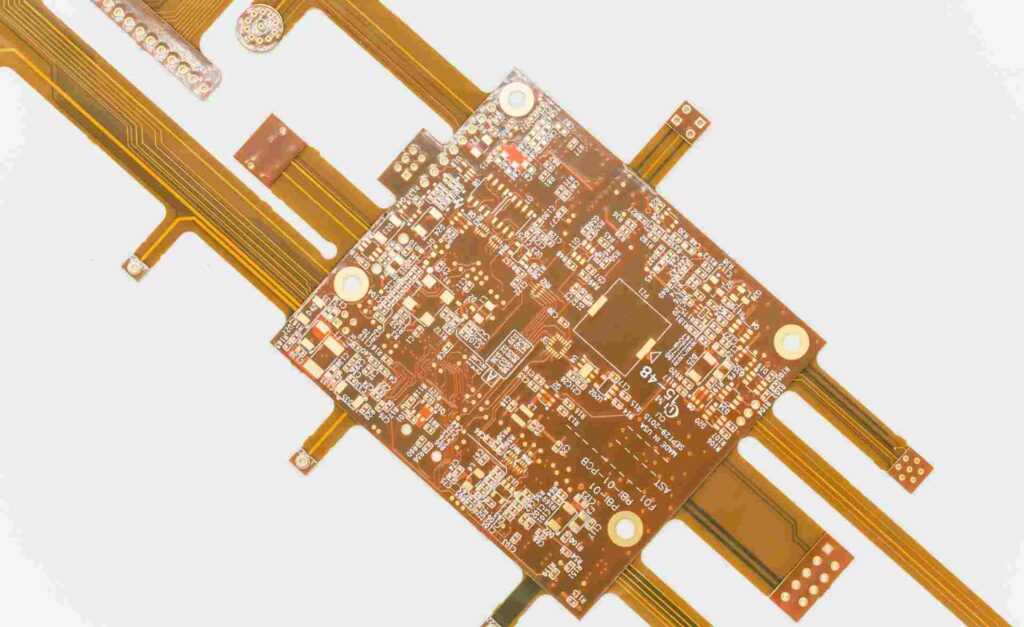
Some applications combine rigid and flexible PCB technologies into a hybrid rigid-flex PCB. These have flexible sections interconnected by rigid sections to get the best of both worlds. The rigid parts provide stability for component mounting while the flex sections allow convenient interconnections.
Hybrid rigid-flex PCBs offer advantages like:
- Ability to fold and package complex electronic hardware in smaller volumes
- Reduced system wiring errors through integrated interconnects
- Lightweight construction compared to using separate rigid PCBs
- Three-dimensional layout capability
- Reduced assembly and part costs
However, they have higher fabrication complexity and costs than pure rigid or flex PCBs. Rigid-flex PCBs are ideal when space savings, weight reduction, and complexity are critical design factors.
Summary
- Flexible PCBs use thin, bendable polyimide substrates to create lightweight, thin circuits that can be dynamically flexed. They are best suited for compact applications like wearables, medical devices, robotics, and consumer electronics.
- Rigid PCBs use stiff glass epoxy substrates that can support denser, more complex wiring patterns and heavier components. They are the workhorse of computers, servers, industrial electronics, automotive electronics, and home electronics.
- Rigid PCBs dominate volume manufacturing due to their low cost. But flex PCB usage is rising due to demand for smaller, lighter electronics.
- Hybrid rigid-flex PCBs provide a good compromise by integrating flexible and rigid sections according to assembly and interconnect requirements.
Flexible vs Rigid PCBs Frequently Asked Questions (FAQ)
Here are some common questions regarding flexible PCBs vs rigid PCBs:
Q: How are components mounted on flex PCBs?
A: Flexible PCBs cannot support heavy through-hole components. Only smaller surface mount devices (SMDs) can be attached using conductive epoxy or soldering. Flex PCBs also often use dedicated flex connectors instead of soldered connectors.
Q: At what size do rigid PCBs become too big and complex to manage?
A: Rigid PCB sizes over about 15” x 20” with multiple high density layers become highly complex to design and manufacture. They require careful placement of multiple vias and jumpers for routing which adds cost. Beyond this size, a rigid-flex PCB design should be considered.
Q: Are rigid PCB substrates limited to just FR4 and FR1 materials?
A: While FR4 glass epoxy is the most popular and cost effective rigid PCB substrate today, other materials like CEM-1 paper epoxy, polyimide, and Arlon thermoplastic are used for more demanding electrical or thermal requirements.
Q: Can traces be printed on both sides of flex PCBs?
A: Single sided flex PCBs dominate the market currently. Double sided flex PCBs are feasible but require special adhesives and via processes so they remain flexible. This quickly becomes complex and expensive.
Q: What are some ways rigid PCBs can be made more flexible?
A: Rigid PCBs can be made more dynamic bending friendly by using thinner substrates (~0.8mm), fewer layers, smaller components, soldered flexible ribbon connections, and reinforced corner mounting points. But they have limits on flex capability compared to pure flex PCBs.


Leave a Reply