What is a Flexible Printed Circuit (FPC)?
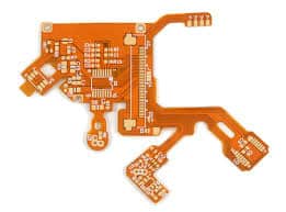
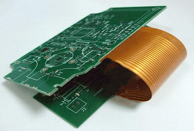
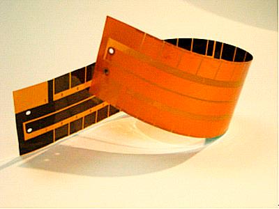
A flexible printed circuit (FPC) is a type of electronic circuitry that is printed or bonded onto a flexible substrate like polyimide or polyester. The flexible substrate allows the circuit to bend and flex while still maintaining electrical connectivity. FPCs are often used in applications where flexibility, space savings, or vibration resistance are required.
Some key characteristics of FPCs:
- Printed wiring traces rather than wires or cables
- Flexible polyimide, polyester, or other plastic substrates
- Can be bent, folded, twisted, and shaped
- Thin, lightweight, and takes up less space
- Withstands vibration and flexing conditions
- Used to interconnect PCBs or connect components
FPCs provide many advantages over traditional wire harnesses or ribbon cables including:
- Space and weight savings
- Improved reliability with fewer interconnected joints
- Easier assembly and integration
- Design flexibility – can shape circuits to fit products
- Withstand vibration, movement, and flexing conditions
FPCs are commonly found in consumer electronics, automotive applications, aerospace, medical devices, industrial equipment and more.
FPC Design and Construction

FPCs consist of conductive traces that are etched or printed onto a thin, flexible substrate using processes similar to those used to make rigid printed circuit boards (PCBs). However, FPCs use flexible base materials that can be bent and shaped instead of rigid FR-4 or other stiff substrates.
Typical cross-section of a flexible printed circuit board. Source
The most common materials used in FPC construction include:
- Base Material: Polyimide, polyester, PEN, PET, or composite materials. Provides the circuit flexibility.
- Conductors: Copper traces, typically 18um to 70um thickness. Other metals like aluminum or silver can also be used.
- Cover layer: Acrylic, polyimide, or epoxy. Protects the conductor traces from damage.
- Adhesive: Bond flex layers and provide insulation between traces.
- Stiffener: FR-4 or polyimide layers to provide rigidity in certain areas.
- Connectors and vias: Interconnect FPC layers and attach components.
FPCs can be single sided with traces on one side, double sided with traces on both sides, or multilayer with 3 or more trace layers laminated together. Shielding, protective covers, and stiffeners can also be incorporated into the design.
FPC Manufacturing Process
Producing flexible printed circuits involves specialized print and etch processes suitable for flexible substrates. The manufacturing process typically includes:
1. Design and Layout
The circuit layout is designed and paths are routed similar to a rigid PCB layout. CAD tools specifically for flex circuits are used.
2. Base Material Lamination
Sheets of the flexible substrate (polyimide, PET, etc) are laminated with adhesive to the desired thickness.
3. Copper Foil Application
Copper foil is bonded to one or both sides of the laminated base material.
4. Photolithography
A photosensitive resist (photoresist) is applied on top of the copper foil. The circuit layout patterns are then transferred to the resist using an exposure and development process.
5. Etching
The exposed copper is etched away, leaving only the protected circuit traces.
6. Resist Stripping
The remaining photoresist is stripped away, revealing the finished copper circuit traces.
7. Coverlay Application
A protective cover layer is applied over the circuitry. Openings are laser cut or etched for connections.
8. Final Processing
Electrical testing, visual inspection, singulation into individual circuits, and electrical connections are completed.
FPC vs Rigid PCBs
Flexible PCBs have some different characteristics compared to their rigid counterparts:
| Parameter | Flexible PCB | Rigid PCB |
|---|---|---|
| Substrate Material | Polyimide, PET, PEN | FR-4, CEM, Rogers |
| Thickness | 25um – 150um typical | 1.6mm typical |
| Layers | 1- 12 | 2 – 32+ |
| Bend radius | As low as 1mm | None |
| Weight | Lightweight | Heavier |
| Temperature resistance | 130°C-180°C | >180°C |
| Chemical resistance | Good | Excellent |
| Cost | Higher | Lower |
As seen above, FPCs tend to be thinner, lighter, and more bendable but have lower temperature resistance compared to rigid boards. FPCs also tend to be more expensive due to specialized materials and manufacturing.
FPC Applications

Flexible printed circuits are used in a wide range of applications across many industries. Some common applications of FPC technology include:
Consumer Electronics
- Mobile phones, laptops, tablets
- Wearables, hearables, fitness trackers
- VR headsets, game controllers
- Displays, OLEDs
Automotive
- Instrument panels, infotainment
- Mirror and light adjusters
- Seat heaters, sensors
Medical
- Hearing aids, implants
- Wearable monitors, patches
- Endoscopes, catheters
Industrial
- Robotics, cobots, UAVs
- Printers, scanners, POS equipment
- IoT and wireless sensors
Aerospace
- Satellites, space vehicles
- Avionics, guidance systems
Some key reasons FPCs are used in these applications:
- Tight space constraints require thin, bendable circuits
- Vibration resistance
- Weight reduction
- Flexible shape and configuration
- High-density interconnections
As electronics become smaller and more lightweight, FPCs will continue growing in popularity across many end products and industries. Their flexibility enables innovative and compact product designs not possible with rigid boards.
Key FPC Design Considerations
Designing and specifying FPCs requires some unique considerations to ensure performance, reliability, and manufacturability:
Bend radius – Avoid tight folds and bends below the minimum bend radius as this can fracture copper traces. Inside bend radii down to 1mm are possible.
Flex life – Evaluate the product’s required folding cycles and flexing conditions to select FPC materials that can withstand long flex life.
Layer stackup – Determine the needed number of copper layers and dielectric materials to provide electrical performance and reliability.
Conductor layout – Position traces along the neutral bend axis where possible. Avoid traces perpendicular to the bend direction.
Stiffener integration – Add stiffeners on sections that require rigidity for connectors, components, etc.
ESD protection – FPCs are prone to ESD damage. Protective covers and grounding can help.
Thermal management – Heat can accelerate FPC wearout. Use thermal adhesives or inserts if high temperature components are attached.
Testing – Environmental stress screening including flexure, torsion, and vibration is recommended to verify robustness.
With careful design considerations, FPCs can reliability withstand millions of flex cycles and provide long operating life in dynamic flexing conditions.
Future Directions for FPC Technology
As flexible electronics continue advancing, FPC technology is evolving in some key areas:
- Higher densities – Finer circuit traces and spaces enable compact, high-pin-count interconnects. Densities over 20 traces/mm are now possible.
- Embedded components – Passives, actuators, and other components are being embedded into the flex layers to enable highly integrated systems.
- Multi-functional materials – FPC materials with biometric, sensing, actuation, and other functionality are being developed.
- 3D structuring – Flex layers can be folded, twisted, and formed into complex 3D shapes and structures.
- Additive manufacturing – Printed electronics techniques like inkjet printing will allow rapid direct FPC fabrication without etch processing.
- Stretchable circuits – Hyperelastic polymer substrates support FPCs that can stretch and deform well over 100%.
These innovations will open up new applications for FPC technology across wearables, medical devices, robotics, and other dynamic markets.
FPC Material and Cost Considerations
Several factors affect the material costs of FPCs:
- Base substrate – Polyimide is most common but PET, PEN, composite blends can provide different properties.
- Lamination – More layers and thinner dielectrics increase costs. 12-16 layer FPCs are common.
- Conductor – Copper is standard. Alternative metals like aluminum or silver increase cost.
- Trace width/spacing – Finer traces and tighter pitches require tighter tolerances and increase cost.
- Covers and coatings – Protective coverlayers, solder masks, surface finishes add cost.
- Adhesives – Acrylic or epoxy adhesives are used to bond layers.
- Stiffeners – Addition of stiffener materials in flex areas adds cost.
- High-frequency materials – RF/microwave flex circuits require specialized low-loss laminates.
- Certifications – Testing/approvals like UL recognition add cost.
In general, FPC cost depends on size, layer count, density, materials, and order volume. Typical cost range is $2 – $10 per square inch.
Major FPC Manufacturers
Some leading flexible PCB manufacturers include:
- Samsung Electro-Mechanics
- Career Technologies
- Flexium Interconnect
- Fujikura Ltd
- SI Flex
- MFS Technology
- Flex Ltd
- AKM Electronics
- Sumitomo
- Multi-Fineline Electronix (MFLEX)
Many traditional rigid PCB fabricators have also invested in flexible circuit production capabilities to meet growing demand.
Both captive fabs within electronics companies and merchant manufacturers produce flexible circuits for various industries and applications. Most FPC suppliers have facilities globally to serve different regional markets.
FPC Assembly and Connections
Assembling components and making connections to FPCs requires specialized approaches:
Assembly techniques
- SMT assembly – compatible with standard SMT assembly processes
- Connector attachment – mechanical clamping or soldering
- Chip-on-flex – bare die or flip chips mounted directly on traces
- Conductive adhesives – for flex component attachment
- Reflow soldering – vapor phase or convection reflow ovens
Interconnection methods
- Anisotropic conductive film (ACF) – conductive particles provide z-axis connections
- Elastomeric connectors – zebra strip or other compressible strips
- Board-to-board connectors – high density flex-to-flex connections
- Crimped terminals – avoid soldering with mechanical crimped pins
- Soldering – reflow or hand soldering where needed
Careful process control is needed to avoid damaging FPCs during assembly while attaining reliable interconnections.
FPC Testing and Inspection
Thorough testing and inspection of FPCs is crucial given their dynamic flexing conditions and susceptibility to defects:
- Visual inspection – microscope inspection of traces, spacing, features
- Automated optical inspection (AOI) – scans circuits for defects and anomalies
- Electrical testing – verifies continuity, resistance, and function
- Bend and torsion testing – validates flexural durability and robustness
- Environmental stress screening – combines temp, humidity, flexing cycles
- Cross-section analysis – verifies layer alignment, adhesion, and plating quality
- Impedance testing – important for controlled impedance flex circuits
- X-ray inspection – detects cracks, voids and internal flaws
Strict process controls combined with comprehensive testing ensures the reliability and performance of flex circuits over their operating lifetime.
FPC Handling and Care
FPCs require careful handling to avoid damaging the flexible material:
- Use antistatic gloves when handling unprotected circuits
- Store in humidity controlled environment to prevent moisture absorption
- Avoid kinking, creasing, folding, or twisting past bend radius
- Prevent foreign object damage from tools or debris
- Use cutting mats and soft-tip tweezers to minimize scratches
- Keep work surface clean to avoid particle contamination
- Use protective covers, reels, or tubes for handling and shipping
With proper care, FPCs can provide reliable performance in dynamic flexing products and challenging environments.
FPCs FQA
Here are answers to some frequently asked questions about flexible printed circuits:
Q: How are components mounted onto FPCs?
A: Surface mount components are commonly used with FPCs. Solder paste is screen printed or dispensed onto pads, components placed, then reflow soldered. Alternatively, conductive adhesives can attach components. Bare die or flip chips may also be directly mounted.
Q: Can FPCs be tested like rigid PCBs?
A: Yes, similar testing like in-circuit test, flying probe, and functional test can be performed on FPC assemblies. Fixtures provide support while probing delicate FPC materials. Additional flexure and bending tests are also advised.
Q: Are FPCs susceptible to thermal stresses?
A: Yes, temperature fluctuations can induce expansion/contraction stresses along the length of traces. Careful thermal design and management is required, especially when attaching heat generating components.
Q: How small of a bend radius can FPCs handle?
A: Some FPC materials can be bent or folded to inside radii below 1mm. This depends on conductor thickness, flexing cycles, and material properties. Dynamic flex testing is recommended.
Q: Can components be embedded or printed directly onto FPCs?
A: Yes, techniques like chip-on-flex and printed electronics allow components and circuitry to be directly integrated onto the FPC layers during fabrication for highly compact systems.


Leave a Reply