Introduction to Flexible Printed Circuit Boards
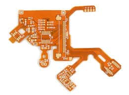
A flexible printed circuit board (FPCB) is a type of printed circuit board that is made with flexible insulating substrate materials. Unlike traditional rigid circuit boards, FPCBs can be bent and flexed without damage during use. This allows them to be integrated into applications where flexibility is required, like wearable devices, medical devices, consumer electronics and more.
FPCBs provide several advantages over rigid boards:
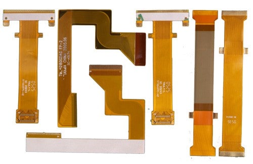
- Flexibility – Can be bent, twisted and shaped to fit mechanically challenging spaces. This enables innovative and compact product designs.
- Lightweight – Weigh less than rigid boards, important for portable devices.
- Thin profiles – Extremely thin (as low as 13um) to fit into the smallest spaces.
- High reliability – Dynamic flexing does not crack solders or traces like rigid boards.
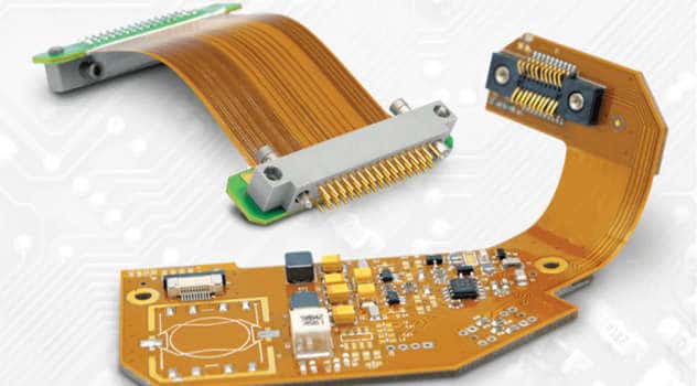
- Simpler assembly – Integrated flex-to-board connectors eliminate connectors and simplification assembly.
To achieve these benefits, FPCBs are made with specialized flexible substrate and conductive materials, which will be covered in this article.
Flexible Substrate Materials
The flexible substrate is the base insulating material upon which circuits are built in FPCBs. The substrate must meet several mechanical and electrical requirements:
- Withstand repeated dynamic flexing without fracturing
- Retain stable electrical properties during flexing
- Good dielectric strength and electrical insulation
- Capable of withstanding PCB processing chemicals and temperatures
- Adequate thermal properties for most applications
Several types of flexible substrate materials are commonly used:
Polyimide Film
Polyimide film is the most common FPCB substrate. It goes by several brand names including Kapton (DuPont) and Apical (Kaneka). Polyimide has:
- Extremely high flex life (>5 million flex cycles)
- Operable from -269 °C to +400 °C
- Excellent chemical resistance
- High tensile strength and tear resistance
Polyimide’s thermal and chemical stability allow it to withstand PCB fabrication processes. The films can be made in thicknesses down to 13um for ultra-thin and flexible circuits. The main limitations are weaker dielectric properties and higher cost than some other substrates.
Polyester Film
Polyester films like Mylar (DuPont) and Melinex (DuPont Teijin) offer a lower cost alternative to polyimide. Key properties:
- Moderate flex life of 50,000 – 100,000 cycles
- Usable from -70 °C to +150 °C
- Lower dielectric strength than polyimide
- Hydrolytic instability limits use in high humidity
Polyester FPCBs meet the cost and performance needs of many consumer electronics and other moderate life and temperature applications.
Liquid Crystal Polymer
Liquid crystal polymer (LCP) films offer the highest performance thermoplastic substrate for FPCBs. Key features:
- Extremely high melting point of 280 °C
- Hydrolytically stable, can be used in high humidity
- Low moisture absorption
- Excellent electrical properties
- Better high frequency signal performance than polyimide
LCP enables FPCBs to withstand very high temperatures during processing and in end-use environments like automotive electronics near hot engines. The excellent electrical properties also suit LCP for high frequency applications like 5G antennas. The downside is substantially higher cost than polyimide or polyester.
Other Substrate Materials
Other flexible substrate materials used in niche FPCB applications include:
- PEEK (polyether ether ketone) – extreme temperature resistance
- PI/glass fabric composites – high tear strength
- PET (polyethylene terephthalate) – lower cost than polyester
- FEP (fluorinated ethylene propylene) – excellent chemical resistance
- PEN (polyethylene naphthalate) – very low moisture absorption
The next section will explore the conductive materials used for traces, pads and other conductive patterns on flexible substrates.
Conductive Materials for Flex Circuits
The conductive traces, pads, antenna patterns and other circuit features on FPCBs are primarily made from rolled annealed copper foil. A thin layer of copper is bonded to the substrate, then circuits etched into it through photolithographic processes identical to rigid PCB fabrication.
Compared to rigid boards, FPCBs use much thinner copper foils, down to 8 microns versus 35 microns, to retain flexibility. The thinner material increases resistivity, so very thin traces may need to be made wider to compensate.
FPCB conductors go through extreme mechanical stresses during flexing. This can lead to cracking or delamination over time. Therefore, properties like ductility and bond strength to the substrate are also very important.
Some key copper foil properties for optimal flex circuit performance:
- High purity to maintain conductivity
- Fine grain structure for flexibility
- Good ductility and elongation
- Matte surface finish to enhance bond to substrate
- UL listed for safety
In high frequency applications, copper can be replaced by lower resistance silver plating to improve performance and lower losses. Other specialty conductive materials like conductive inks or epoxies may be applied as well.
Next we will look at some ways that FPCB construction can be optimized for maximum flexibility and life.
Optimizing Flexible Circuit Construction
While the materials themselves are flexible, aspects of FPCB construction must also be optimized to avoid rigid sections or fragility during repeated flexing:
Coverlayers
Coverlayers are thin insulating films laminated over the top conductor layer of the circuit. Polyimide is typically used. This protects the delicate copper from abrasion and prevents shorting between traces.
Adhesives
Flexible adhesives are used throughout FPCB construction. Non-rigid acrylic, urethane and epoxy adhesives bond layers without reducing flex life or creating rigid sections.
Stiffeners
Selective use of stiffeners made from materials like polyimide or FR4 can strategically rigidize portions of the circuit that do not require flexing. This prevents unwanted bending that could damage solder joints or traces.
Enclosures
Properly designed mechanical housings guide and control the flexing of the circuit into optimal shapes, preventing damage from uncontrolled random bending.
Trace Design
Traces should be oriented along the bend axis as much as possible. This avoids tensile stresses perpendicular to the traces during flexing.
Connection Design
Solder pads, connectors and other connections must be able to withstand dynamic mechanical stresses from bending. Specially designed flex-to-board connectors are often used.
Thoughtful design and material selection creates durable, long-life flexible circuits.
Testing and Qualifying Flexible Circuits
New FPCB designs should go through qualification testing to verify that performance will meet requirements over the desired lifetime:
- Flex testing – FPCB is dynamically flexed through required angles for thousands of cycles, often while environmental factors like temperature or humidity are applied. Electrical continuity is monitored for failures.
- HASS testing – Various harsh environmental conditions like temperature cycling or vibration are applied for extended durations to uncover potential weaknesses.
- Cross-section analysis – Microscope inspection of cross-sectioned FPCB samples before and after testing reveals internal material failures, delamination issues, cracks, etc.
- Soak testing – FPCB is exposed to elevated temperature and humidity for extended periods to reveal potential material degradation.
- Electrical testing – Dielectric strength, insulation resistance, impedance and other key electrical parameters are measured before and after qualification testing.
Extensive testing demonstrates that the FPCB construction and materials selected will survive the mechanical and electrical rigors of the intended application over the desired operational lifetime.
Common Applications of Flexible Circuits
The unique benefits of FPCBs have led to adoption across a wide range of applications:
- Consumer Electronics – Cell phones, tablets, wearables, VR/AR headsets
- Automotive – Sensors, circuits near hot engines, dynamic displays
- Medical – Catheters, implanted devices, patient monitors
- Industrial – Robotics, automation and motion control
- Defense – Missiles, satellites, navigation systems
- Aerospace – Avionics, inflight entertainment, engine sensors
And many more. Anywhere that flexibility, low weight, or space savings are beneficial, FPCBs deliver advantages over rigid boards. With the proliferation of wearable and Internet of Things devices, flexible circuits will continue seeing increased usage.
Conclusion
Flexible printed circuit boards unlock innovations in product design with their ability to dynamically bend and flex without damage. Polyimide is the most common FPCB substrate, but alternatives like LCP handle extreme temperatures and humidity. Construction techniques like selective stiffening and flex-friendly connections enable high reliability. With rigorous testing, FPCBs can survive millions of flex cycles in the harshest conditions across many industries. The unique properties of flex circuits will enable compact and clever product designs well into the future.
Frequently Asked Questions
What are the main differences between rigid PCBs and FPCBs?
The main differences are:
- Flexible substrate – FPCBs use thin plastic films instead of rigid FR4.
- Thinner copper – Much thinner copper foils are used to retain flexibility.
- Specialized design – FPCB layouts and connections are optimized for flexing.
- Dynamic flex – FPCBs are designed to bend repeatedly without damage.
- Lightweight – Weigh less than rigid boards.
- Thin – Extremely thin vertical profile.
How do you repair a damaged flexible PCB?
Minor FPCB damage like a cut trace can be repaired by patching with conductive epoxy. For more significant damage, the damaged section is often cut out and replaced with a jumper wire or new piece of flex circuit. If damage is extensive, full replacement of the FPCB may be required.
What are stiffeners used for in FPCBs?
Stiffeners made from materials like polyimide are selectively applied in areas of FPCBs that do not require flexing. This creates strategic rigid sections to prevent unwanted bending that could damage solder joints, traces or connectors.
How small can FPCB circuits be made?
The limits keep shrinking as fabrication processes improve. Traces and spaces down to 15 microns are common, with some FPCBs achieving 8 microns. Entire circuits can be made under 0.1 mm thick.
What are some key considerations when designing an FPCB?
- Orientation of traces and components for optimal flexing
- Minimizing rigid sections
- Robust connection systems to withstand flexing
- Controlling/limiting bend radii to avoid damage
- Allowing for elongation of traces during bending
- Thermal management with minimal rigid materials


Leave a Reply