Introduction
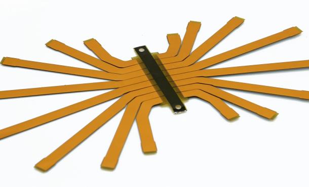
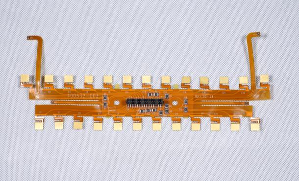
A flexible printed circuit board (FPCB) is a type of printed circuit board made of a flexible insulator such as polyimide or polyester. FPCBs are thin, lightweight, and can bend and flex during use. They are commonly used in consumer electronics, medical devices, automotive applications, and other products where flexibility, space savings, or weight reduction are required.
FPCBs offer several advantages over traditional rigid circuit boards:
- Flexibility – Can be bent, folded, twisted, and shaped to fit mechanical designs with moving or dynamic parts. This allows packaging in tight spaces.
- Light weight – Thinner and lighter than rigid boards. Helps reduce product weight.
- Reliability – Flex-to-flex dynamic flexing distributes stress across the entire assembly. This improves reliability and product life.
- Customization – Can be customized for specialized designs and form factors. Complex 3D wiring paths are possible.
- Cost – Lowers assembly costs by enabling direct attachment of components. Reduces connectors needed.
FPCB construction, manufacturing processes, component assembly, and applications will be explored in detail in this article.
FPCB Construction and Materials
FPCBs consist of conductive copper traces bonded to a thin flexible dielectric base. The main components are:
- Base Material – Typically polyimide or polyester films around 25-100 μm thick. Provides electrical insulation and mechanical support.
- Conductors – Copper foil around 12-35 μm thick. Forms the conductive traces and pads.
- Bonding Adhesive – Joins the base film and copper foil. Provides adhesion and prevents delamination.
- Coverlay – A solder mask layer that protects traces from damage and prevents shorts.
- Stiffener – Optional rigid section for component mounting or connection. Improves handling.

The flexible base material is the key factor determining the physical properties of the FPCB. The most common base films include:
- Polyimide (PI) – High strength, heat resistant up to 400°C. Used for high reliability applications.
- Polyester (PET) – Lower cost but has lower temperature resistance around 105°C. Suitable for consumer products.
- Others – Polyamide, PEN, PEEK. Specialty films with specific temperature, chemical, or mechanical properties.
Conductors are typically rolled annealed copper foil. Thicker copper provides better conductivity but reduces flexibility. Common sizes are 12 μm, 18 μm, and 35 μm thick. The foil is bonded to the base film with acrylic, epoxy, or polyimide adhesive.
FPCB Manufacturing Process
Flexible PCBs are produced through a sophisticated fabrication process with similarities to rigid PCB manufacturing. The basic FPC manufacturing steps are:
1. Base Material Preparation
The flexible base film, typically polyimide or polyester, is loaded onto process rolls. Pre-treatment cleans the material and applies an adhesion promotion coating or liquid bonding adhesive.
2. Copper Foil Lamination
Rolls of copper foil are pressed onto the base material using heat and pressure. This bonds the layers together with the help of the adhesive. Single-sided or double-sided lamination is possible.
3. Photolithography
A photoresist coating is applied on the copper layers. The PCB design pattern is then optically transferred using ultraviolet light exposure through a photomask. Photoresist is developed, leaving bare copper traces exposed.
4. Etching
Exposed copper is etched away chemically, while protected traces remain. This forms the conductors in the desired PCB layout. Both wet etching and dry etching methods are used.
5. Photoresist Stripping
Remaining photoresist coating is stripped away, leaving just the copper circuit design on the base film.
6. Coverlay Lamination
A solder mask coverlay layer is often laminated onto the flexible circuitry for insulation and protection. Openings in the coverlay expose solder pads.
7. Solder Mask
Solder mask may be applied as a liquid instead of using laminated coverlay. This covers copper traces while leaving contacts exposed.
8. Finishing
Edge trimming, electrical testing, and other finishing steps complete fabrication. The FPCBs are then separated into individual boards or supplied on process rolls.
Component Assembly and Connections
Building components onto the fabricated FPCB involves specialized assembly methods:
- SMT – Surface mount devices are commonly used. High temperature SMT is limited by the base material properties.
- Conductive Adhesives – Isotropically conductive adhesive films can assemble components and make electrical contacts.
- Plated Half-Etching – For thick copper sections that allow soldering or component terminations.
- Mechanical Clamping – Can press-fit flex tails into connectors without soldering.
- Anisotropic Conductive Film (ACF) – Used to thermocompression bond fine-pitch components.
Connections from the FPCB to external circuitry can be made via:
- Pads/Terminals – Exposed solderable pads along the flex board edge.
- Plated Through Holes – Holes allowing solder fillets and connections through the board.
- Flex Tails – Extending flexible sections with exposed traces for insertion into connectors.
- Zebra Strips – Alternating conductive and insulative fingers inserted into mating connectors.
FPCB Applications
The thin, lightweight, and dynamic nature of FPCBs allow them to be used in many applications where rigid boards are impractical. Some typical uses include:
Consumer Electronics
- Mobile phones – Interconnect various hinged and sliding sections
- Laptops and tablets – Foldable interconnect within screen and keyboard
- Wearables – Used in smartwatches and activity trackers
- Camera modules – Flexible connections to CMOS image sensors
Automotive
- Flex circuits for door harnesses, seat heaters, mirror adjustments
- Dynamic flexing helps improve reliability in vibrational environments
Medical
- Hearing aids – Allows fitting into ear canal shape
- Imaging devices like endoscopes
- Wearable health monitors
Industrial
- Robotics – Moving joints and manipulators
- Fitness equipment – Flex circuits used in exercise machines
- Aviation control systems
Other Advantages
- Allow stacking of circuit layers for increased connection density
- Integrate circuits directly onto the flex board
- Enable roll-to-roll manufacturing processes
- Cost reductions by eliminating connectors and simplifying assembly

FPCB Design Considerations
Designing and laying out FPCBs requires special considerations for the flexible material properties:
- Bend radius – Avoid sharp folds. Use generous bend radii larger than minimum specified by base material.
- Dynamic flexing – Design for repeated bending cycles without metal fatigue or wear.
- Stiffener locations – Strategically place rigid sections for component mounting and connections.
- Trace widths and spacing – Account for flexibility effects on conductors.
It is critical to communicate the intended use conditions, flexing motion, and mechanical constraints to your FPCB manufacturer during design. Material selection, layer stackup, and layout can then be optimized accordingly.
FPCB vs Rigid-Flex PCBs
FPCBs provide full flexibility, while rigid-flex boards combine both rigid and flexible substrates for more complex designs:
- Fully flexible board able to dynamically bend.
- Limited component mountingoptions.
- Typically simpler, low-layer count designs.
- Lower fabrication cost.
Rigid-Flex PCB
- Combines rigid sections for components with flexible interconnects.
- More complex, multilayer designs possible.
- Allows high density and complex routing.
- More expensive but highly customizable.
Future Outlook
Flexible printed circuits will continue gaining popularity and wide use in consumer electronics, wearables, medical devices, automotive, and industrial products. The global FPC market reached $13.7 billion in 2021 and is forecasted to grow around 6% annually through 2028.
Key trends driving adoption include:
- Increasing utilization in smartphones, laptops, cars, and IoT devices.
- Enabling innovation in flexible displays and electronics.
- Demand for smaller and lighter products.
- Growth in high-speed applications like 5G devices.
- Expanding wearable and healthcare electronic markets.
FPC technology allows packing more functionality into ever-smaller flexible form factors. With rising demand and continued improvements in materials and fabrication, flexible PCBs will remain an essential core technology across many industries.
Frequently Asked Questions
Q: What are some typical FPCB thickness values?
A: FPCB thickness generally ranges from about 25 μm to around 200 μm. Typical values are:
- Single layer: 25-50 μm
- Two metal layers: 50-80 μm
- Multilayer: 80-200 μm
Thicker boards are stronger but less flexible. Thinner FPCBs below 50 μm can be very fragile and challenging to handle.
Q: How many copper layers can you have in an FPCB?
A: Most flex circuits are single or double sided, but more advanced multilayer FPCBs are possible with up to 6, 8, or 10 metal layers. As layer counts increase, the boards become thicker and less flexible. High density interconnects are enabled but require more complex lamination processes.
Q: What line and space rules are common for FPCB traces?
A: Typical flex PCB trace widths and spacing are:
- Line width: Minimum 25-50 μm
- Line space: Minimum 25-100 μm
Finer traces down to 15 μm widths are possible but require tighter process control. Wider spacing improves reliability and reduces shorts from dynamic bending.
Q: How are components attached to FPCBs?
A: Common FPCB component attachment methods include:
- SMT soldering
- Conductive adhesive films
- Mechanical clamping or press-fit
- Anisotropic conductive film (ACF) bonding
- Plated half-etched pads for solder or wire bonding
The assembly method depends on conductor thickness, pitch, and component types.
Q: What are some alternatives to polyimide for FPCB base films?
A: Other common FPCB base dielectric films include:
- Polyester (PET) – Lower cost, lower temp rating
- Polyamide (PA) – Semi-flexible option
- PEN – Higher temp rating than PET
- PEEK – For very high temp or harsh environments
Choosing the right base material depends on flexibility, temperature, chemical, and mechanical requirements.


Leave a Reply