Introduction
Flexible printed circuits (FPCs) have become an integral part of modern electronics due to their ability to bend and flex to fit into tight spaces. As flexible PCBs grow in popularity, it’s important for PCB designers to understand the properties and applications of the various flexible circuit materials available. This article will provide a comprehensive overview of the most common flexible substrate materials used in PCB fabrication.
Flexible Substrate Materials
There are several factors to consider when selecting a flexible substrate material:
Dielectric Properties
The dielectric constant and loss tangent determine a substrate’s electrical performance. Materials with a low dielectric constant allow tighter trace spacing while low loss materials minimize signal loss.
Mechanical Properties
Flexible materials must withstand repeated bending stresses. Important properties include tensile strength, elongation at break, and flexural endurance.
Thermal Properties
The maximum operating temperature and thermal expansion coefficient impacts soldering processes and reliability under temperature cycling.
Cost
Flexible materials have a wide range of costs depending on material grade, thickness, and complexity.
With these factors in mind, here are the most common flexible substrate materials used in PCBs:
Polyimide (PI)
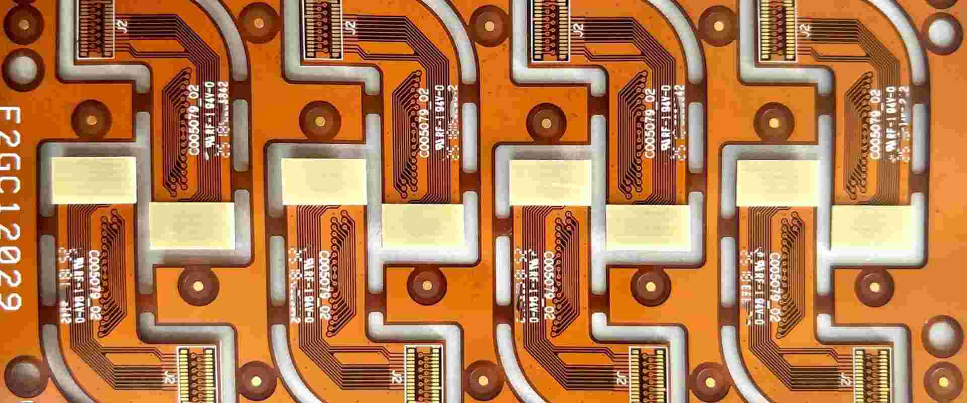
Polyimide films like Dupont’s Kapton or Ube’s Upilex are the most popular flexible PCB materials. Their exceptional mechanical properties and heat resistance allow reliable performance in dynamic applications. Polyimide has good chemical resistance but relatively high water absorption compared to other flex materials.
| Property | Typical Value |
|---|---|
| Dielectric Constant | 3.4 |
| Loss Tangent | 0.002-0.010 |
| Tensile Strength | 231 MPa |
| Elongation at Break | 70% |
| Max Operating Temperature | 260°C |
| Thermal Expansion Coefficient | 20 ppm/°C |
Polyethylene Naphthalate (PEN)
PEN films like Teijin’s Teonex offer improved moisture resistance over polyimide. PEN has a lower dielectric constant but is limited to lower operating temperatures. It provides good flexibility and chemical resistance.
| Property | Typical Value |
|---|---|
| Dielectric Constant | 3.0 |
| Loss Tangent | 0.002 |
| Tensile Strength | 200 MPa |
| Elongation at Break | 40% |
| Max Operating Temperature | 150°C |
| Thermal Expansion Coefficient | 20 ppm/°C |
Polyethylene Terephthalate (PET)
PET films are more economical than polyimide or PEN but have reduced thermal capabilities. PET provides good flexibility and chemical resistance at a lower cost.
| Property | Typical Value |
|---|---|
| Dielectric Constant | 3.2 |
| Loss Tangent | 0.02 |
| Tensile Strength | 150 MPa |
| Elongation at Break | 80% |
| Max Operating Temperature | 120°C |
| Thermal Expansion Coefficient | 20 ppm/°C |
Liquid Crystal Polymer (LCP)
LCP is an advanced flexible material known for its extremely low loss properties. It allows improved signal speed and integrity compared to other flex materials but at a higher cost. LCP has excellent chemical resistance.
| Property | Typical Value |
|---|---|
| Dielectric Constant | 3.0 |
| Loss Tangent | 0.002 |
| Tensile Strength | 82 MPa |
| Elongation at Break | 25% |
| Max Operating Temperature | 170°C |
| Thermal Expansion Coefficient | 17 ppm/°C |
Advantages of Flexible Circuits
Now that we’ve compared the properties of common flexible substrate materials, let’s discuss the unique benefits provided by flex circuits:
- Flexibility – Allows conforming to 3D shapes and dynamic flexing during use
- Thin and lightweight – Provides space and weight savings versus rigid boards
- Reliability – Flexible materials withstand repeated bending without failure
- Simplified assemblies – Eliminates connectors, harnesses, and fasteners
- Design freedom – Curving circuits expand routing options
- Reduced EMI – Tight component spacing minimizes radiation
By understanding the advantages of flexible circuits, PCB designers can take full advantage of this technology in their projects.
Flex Circuit Applications
The useful properties of flex circuits have made them a preferred solution across many industries:
Consumer Electronics
Flexible circuits are ubiquitous in mobile phones, laptops, tablets, cameras, and wearables. Their small size and dynamic flexing are ideal for these applications.
Automotive
Automotive grade flex circuits withstand underhood temperatures and vibration. Flex boards simplify wiring harnesses and are used in sensors and displays.
Medical
Thin flex circuits allow diagnostic and therapeutic medical devices to be minimally invasive. Flexible materials ensure reliability in implantable devices.
Defense/Aerospace
Rugged high-reliability flex circuits withstand vibration and thermal cycling in harsh environments. Flex boards reduce SWaP (size, weight and power).
Industrial
Flex circuits simplify wiring and provide enhanced reliability. Common applications include robotics, automation, IoT devices, and sensors.
This wide applicability demonstrates the versatility of flex circuit technology.
Flex PCB Design Considerations
Designing a reliable flexible PCB requires special considerations:
Dynamic Flexing
Avoid traces crossing high stress areas of frequent dynamic bending. Use wide trace widths for better flex life. Consider possible tear propagation paths.
Layer Stackup
Use thin flexible dielectrics and arrange layers for optimal bending. Stiffeners can be added in rigid sections. Balanced symmetrical stackups aid stability.
Component Mounting
Use flexible encapsulated components rated for flexing. Avoid large or heavy parts in high flex areas. Adhesives must withstand flexing.
Board Stiffening
Strategically stiffen boards with additional layers. Avoid covering bend areas. Use stiffening ribs or frames if needed.
ESD Protection
Flexible circuits require special ESD protection measures since they lack a grounded chassis. Use ESD materials and containment strategies.
Testing
Thoroughly test prototype flex circuits under expected dynamic bending conditions. Fix issues before finalizing the design.
Paying attention to these considerations during the design process will ensure your flex PCB can withstand the rigors of its intended application. Proper flex circuit design leads to successful flexible printed circuit performance.
Frequently Asked Questions
What are the main differences between rigid and flex PCBs?
The main differences between traditional rigid PCBs and flexible PCBs are:
- Rigid PCBs use FR-4 or other rigid insulating substrates while flex PCBs use thin flexible polymer films as dielectrics.
- Flexible circuits can bend and flex repeatedly without damage while rigid boards would fracture under bending stresses.
- Flex PCBs are extremely lightweight and thin compared to rigid boards.
- Flexible materials and circuits are more expensive than typical rigid PCB materials and construction.
- Special design considerations are needed for flex PCBs to ensure dynamic flexing reliability.
Should components be mounted on the rigid or flexible sections of a flex circuit?
For dynamic flexing applications, it is generally best to mount components on the rigid sections of the PCB rather than the flexible areas. Attaching heavy components directly to the flexing regions can put excessive strain on the material and traces, leading to cracks and eventual failure.
Some flexible encapsulated components like resistors or capacitors can be safely mounted on the flexible sections, but any large or heavy parts are better suited for the rigid areas. The flexing portion should be reserved for only trace routing.
How many times can a flex circuit be dynamically bent before failure occurs?
The flex life depends heavily on the substrate material, trace width/spacing, bend radius, and other design factors. Typical values for common materials under moderate bending stress are:
- Polyimide: 10,000 – 100,000 cycles
- PEN: 20,000 – 50,000 cycles
- PET: 50,000 – 100,000 cycles
- LCP: 500,000+ cycles
Narrow traces and tight bend radii also reduce the flex life. The application requirements must be thoroughly considered to ensure the flex circuit’s design supports the expected dynamic bending cycles without failure.
Can flex PCBs be assembled with SMT components and processes?
Yes, flex circuits are fully compatible with surface mount assembly. The same SMT soldering methods used for rigid PCBs can be utilized. However, it is critical to use a rigid stiffener beneath the flex board during assembly to avoid bending and warping issues through solder reflow.
For reliable solder joints, it is recommended to use flexible encapsulated chip components that are rated for flexing applications. Standard rigid SMT components can fracture under bending stresses.
What are some best practices for routing traces on flexible circuits?
Some trace routing tips for flex PCB designs are:
- Use curved traces instead of angular 90° traces
- Avoid traces crossing high stress areas
- Use teardrop pads for better adhesion
- Minimize the number of layers
- Place reference planes 1/3 from outer surfaces
- Maximize trace widths for better flex life
- Use crosshatching for large copper fills
- Strategically stiffen only areas that require it
Following guiding principles like these will lead to a robust flexible circuit layout optimized for bending applications.
Conclusion
Flexible printed circuits provide unique advantages over rigid boards for many modern electronic devices and systems. As PCB designers, having a comprehensive understanding of flexible substrate materials, applications, design considerations, and assembly processes allows us to take full advantage of this technology. By following the guidance in this article when designing your next flex PCB, you can ensure reliable performance in the dynamic bending environments seen across consumer, automotive, medical, defense, and industrial applications.


Leave a Reply