Introduction
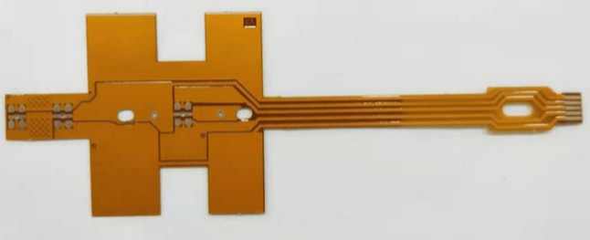
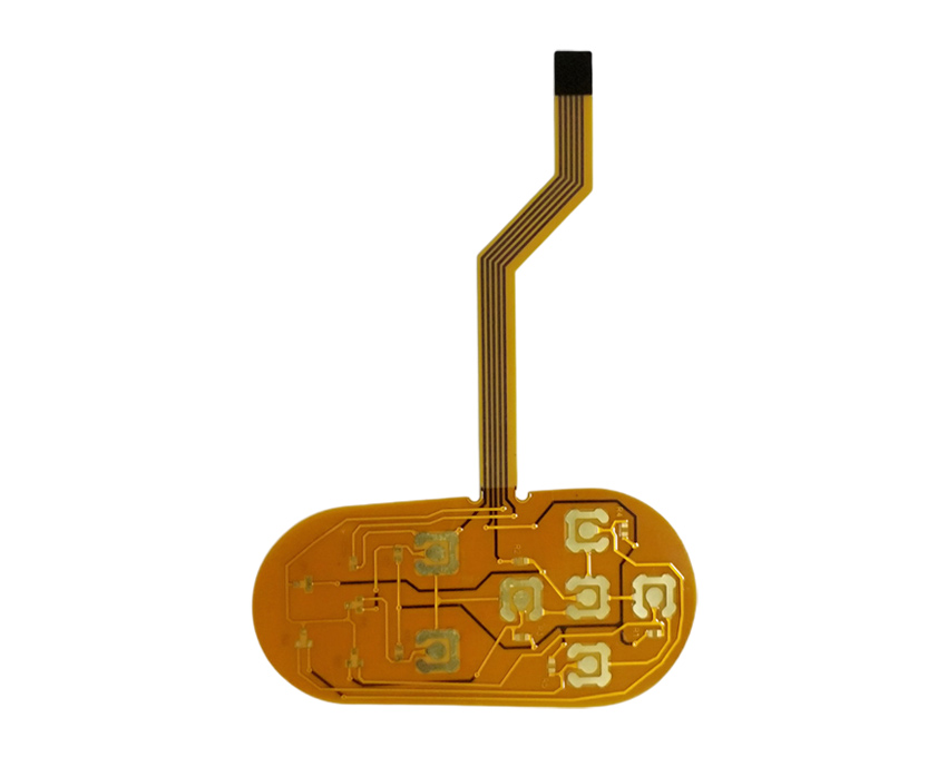
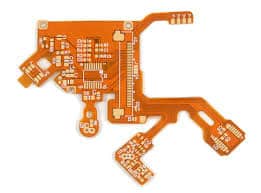
Flexible circuits, also known as flex circuits, are a type of printed circuit board that can bend and flex. They are made from flexible dielectric materials like polyimide or polyester rather than rigid boards like FR-4. Flex circuits enable unique form factors, moving parts, and dynamic flexing in electronic devices and components. They are widely used in consumer electronics, medical devices, aerospace, and automotive applications. This article provides an overview of flex circuit design considerations, materials, fabrication, assembly, and testing for electrical engineers.
Flex Circuit Design Guidelines

Designing a successful flex circuit requires careful planning and engineering. Here are some key guidelines to follow:
Plan for Flexibility
- Identify areas that need to flex or bend. Avoid sharp folds.
- Minimize components in flexing areas. Allow space between components.
- Use flexible solder masks, covers, and adhesives.
- Ensure conductors can flex without damage.
Choose Proper Materials
- Select flexible dielectric films like polyimide or polyester.
- Use conductive materials like rolled annealed copper foil.
- Choose flexible dielectrics and adhesives.
Manage Layer Stackup
- Stackup with thinner, lighter materials enables easier flexing.
- Use thinner dielectrics like 12-25μm polyimide.
- Limit layers or interleave stiffeners to prevent buckling.
Implement Robust Conductor Layout
- Avoid brittle alloys like rolled hardened copper.
- Design traces wider in flex areas for durability.
- Use hatched ground planes for flexibility.
- Isolate high-frequency signals.
Incorporate Stiffening Elements
- Add stiffeners made of polyimide or steel for components.
- Use covers, shields, or metal layers for protection.
- Allow room for stress relief during flexing.
Flex Circuit Materials
Selecting the right materials is critical for manufacturing a functional, reliable flex circuit. Here are key material considerations:
Dielectric Films
Polyimide films like Kapton are most common. Other options:
- Polyester (PET) – Lower cost but less flexible.
- PEN – Similar to polyimide but more temperature resistant.
- Fluoropolymers (PTFE) – Extremely durable and heat resistant.
Conductive Layers
- Rolled annealed copper foil 3-35μm thickness. Annealing makes it flexible.
- Some use of copper alloys like bronze or beryllium copper.
- Nickel/gold finish for soldering or wire bonding.
Bonding Adhesives
- Acrylic or epoxy adhesives attach layers. Flexible options available.
- Heat or pressure activated bonding.
Covercoats and Stiffeners
- Liquid photoimageable solder masks. Flexible after curing.
- Adhesives like silicone or urethane for protecting components.
- Polyimide stiffeners 1-2 mils thick.
Fabrication and Assembly
Producing flex circuits requires specialized fabrication processes:
Patterning Dielectric Films
- Use lithography to image dielectric layers.
- Etch away unwanted areas of copper foils.
- Laser direct imaging can rapidly pattern layers.
Layer Stacking and Alignment
- Align and bond dielectric/conductor layers.
- Build up layer stack with adhesives.
- Drill microvias between layers as needed.
- Treat surfaces for enhanced adhesion.
Conductor and Surface Finishing
- Plate gold or nickel surface finishes as needed.
- Apply solder mask and nomenclature printing.
- Selectively apply stiffeners and shields.
Component Assembly
- Solder paste and reflow assembly same as rigid PCBs.
- Smaller components and finer pitches.
- Wire bonding and conductive adhesives.
- Avoid placing components in high flex zones.
Flex Circuit Testing

Thorough testing ensures flex circuits meet reliability requirements:
Electrical Testing
- Continuity testing of tracks.
- Verify insulation resistance.
- Test for pinholes or other laminate flaws.
Mechanical Testing
- Flex cycles from flat to bent shape.
- Dynamic/vibration testing.
- Torsion and bending tests.
- Measure flexural rigidity.
Environmental Testing
- Thermal cycling over temp range.
- Humidity exposure testing.
- Mechanical testing over temp range.
Inspection
- Dimensional inspection.
- Microscope inspection of traces.
- X-ray imaging.
- Automated optical inspection.
Failure Analysis
- Electron microscopy of cracks/failures.
- Measure adhesion strength.
- Identify root cause of issues.
Flex Circuit Design Examples
Here are a few examples of devices that use flex circuitry and their key design elements:
Wearable Fitness Tracker
- Polyimide flex dielectric.
- Traces routed for dynamic bending.
- Interconnects between rigid and flex areas.
- Soft polyurethane top coating.
Laptop Display Ribbon Cable
- Polyimide film, copper traces.
- Traces spaced for impedance.
- Bonded to stiffener for support.
- Repeated smooth rolling flex motion.
Medical Ultrasound Probe
- Multi-layer polyimide flex circuit.
- Micro coaxial cables and copper traces.
- Connects piezoelements to instrument.
- Dynamic repeated flexing.
Conclusion
Flex circuits enable electronics to take on unique and demanding mechanical requirements. With careful material selection, design practices, assembly methods, and testing, flex circuits can provide reliable performance in millions of flex cycles. As flexible electronics continue to evolve, robust flex circuit design will increase in importance for engineers across many industries.
FAQ
What are the main advantages of using flex circuits?
Some key advantages of flex circuits over rigid boards are:
- Can conform to thin, contoured, or moving shapes.
- Highly customizable and versatile.
- Typically lighter and more space efficient.
- Often higher reliability with dynamic flexing.
- Improved manufacturing efficiency and yields.
What are some examples of flexible materials used in flex circuits?
Common flexible materials include:
- Polyimide films like Kapton for flex dielectric.
- Polyester films (PET) as a lower cost dielectric option.
- Rolled annealed copper foils for conductors.
- Flexible acrylic or epoxy adhesives.
- Liquid photoimageable solder mask.
How are components assembled onto flex circuits?
Standard SMT assembly is used. Components are soldered onto flex circuit pads using solder paste and reflow like rigid PCBs. However, care is taken to avoid placing components in areas that will undergo the most extreme flexing. Adhesives and wire bonding are other assembly options.
How can you test the flexibility and durability of a flex circuit?
Flex testing involves repeated bending, folding, twisting, and flexing while monitoring for electrical and mechanical failures. Tests include flex cycling, dynamic bend testing, vibration, torsional twisting, and measuring changes in flexural rigidity.
How are rigid and flex circuit boards integrated together?
Rigid sections or stiffeners are often bonded to the flex circuit using adhesives. Traces are routed from the rigid to the flexible using layered interconnects. Special fixtures may be required to prevent stresses during assembly.


Leave a Reply