Introduction
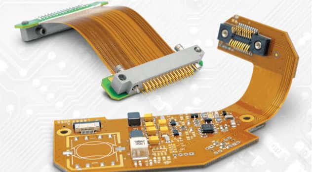
Flexible printed circuit boards (FPCBs) are made from flexible materials that allow them to bend and flex without damage. They are commonly used in consumer electronics, medical devices, automotive electronics, and other applications where a rigid printed circuit board is not suitable. The materials used in FPCBs must be durable, flexible, and able to withstand bending cycles without failure. This article provides an overview of the different materials used in FPCBs and their properties.
Polyimide Film
The base material for most FPCBs is a polyimide film such as Kapton. Polyimide films offer:
- Excellent thermal properties. They have high heat resistance and can withstand temperatures up to 400°C. This allows FPCBs to be soldered.
- Good chemical resistance. Polyimide films are not affected by most solvents.
- High mechanical strength and flexibility. Polyimide films can bend repeatedly without damage.
The polyimide film provides the flexible backbone of the FPCB anddetermines its minimum bend radius. The thickness of the film is typically 12.5 to 100 microns. Thinner polyimide allows tighter bending radii.
Copper Foil
Copper foil is laminated onto the polyimide film to form the conductive traces of the FPCB. The thickness of the copper foil is typically 12-35 microns. Rolled annealed copper is commonly used which offers high ductility and flexibility.
The copper traces are produced by etching away unwanted copper after it is laminated to the polyimide film. This forms the desired conductive pattern. Copper is the ideal conductor due to its high electrical conductivity and versatility with PCB fabrication processes.
Coverlay/Solder Mask
A coverlay or solder mask is applied over the copper traces to prevent short circuits and oxidization. Common coverlay materials include LCP (liquid crystal polymer), polyimide, and silicone. These materials can be sprayed, screen printed, or laminated onto the PCB.
Coverlays protect the copper traces from damage and prevent solder bridging between adjacent traces during assembly. They also help prevent copper oxidation which can degrade performance over time. Flexible coverlay materials are chosen that can bend and flex along with the PCB.
Adhesives
Adhesives are used to bond the different layers of an FPCB together. The adhesive needs to remain robust over the PCB’s lifetime and withstand flexing without delamination or cracking. Common adhesive options include:
- Acrylic: Offers good flexibility and bonds well to polyimide films.
- Epoxy: Provides a strong bond but is less flexible than acrylics. Often used for multilayer FPCBs.
- Polyimide: Adheres well at high temperatures required for PCB processing. Maintains flexibility.
- Silicone: Flexible over a wide temperature range but not as strong a bond as other adhesives.
The adhesive type can be tailored for the specific application requirements of the FPCB design.
Reinforcement Material
For FPCBs that require high flex durability and cycles, reinforcement material is sometimes added. This helps prevent conductor cracking and delamination over repeated bending. Common reinforcement options include:
- Polyimide film: Additional layers of polyimide film help increase strength and durability.
- Fiberglass: Thin fiberglass cloth reinforces the FPCB, often applied with epoxy.
- Polyester mesh: Adds strength while maintaining flexibility. Compatible with high temp processes.
The reinforcement material is typically integrated into the stackup construction along with the adhesive layers. This produces a robust FPCB able to withstand high cycle repetitive bending motion.
Finishes
Special finishes are sometimes applied to the FPCB copper traces or contact areas to enhance properties like solderability or corrosion resistance. Common finishes include:
- OSP (Organic Solderability Preservative): Used to protect copper and makes it more solderable. Very common finish for consumer FPCBs.
- Immersion Tin: Provides excellent solderability while avoiding tin whiskers.
- Immersion Silver: Offers high conductivity and good corrosion resistance.
- ENIG (Electroless Nickel Immersion Gold): Provides excellent corrosion resistance and wear resistance. Common for high-reliability applications.
- Anisotropic Conductive Film (ACF): Used to connect FPCBs by applying conductive adhesive dots. Simpler than soldering for touch screens and displays.
The finish chosen depends on application requirements like cost, soldering process, corrosion resistance, and conductivity needs.
Common FPCB Stackups
FPCBs can be fabricated with different layer stackups. Here are some common configurations:
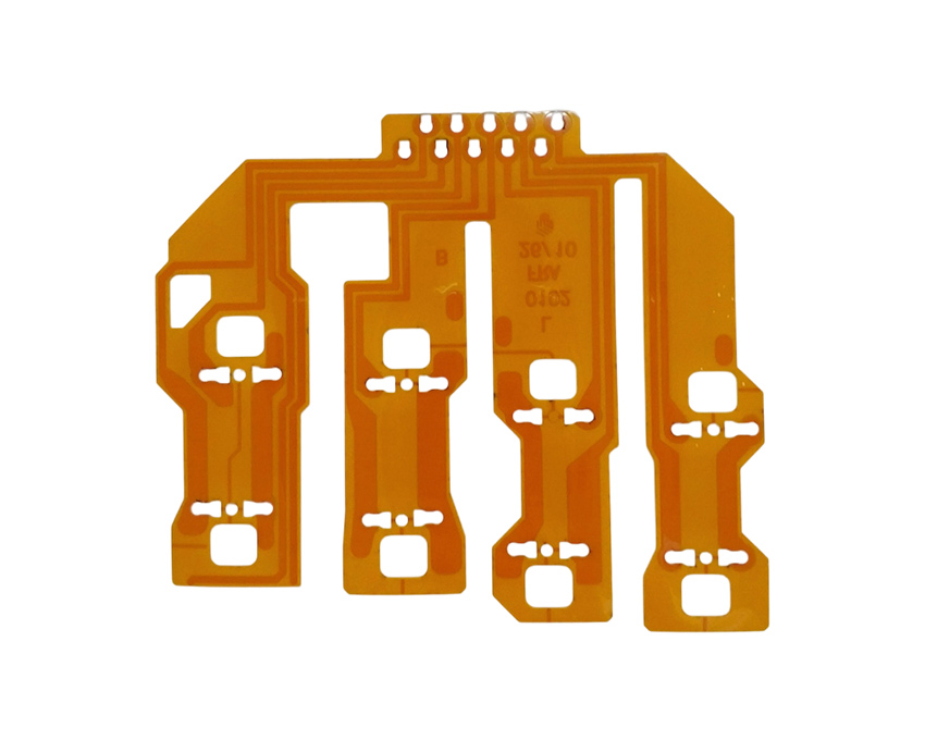
- Single-sided: Copper traces on one side of a polyimide base layer. Simple and inexpensive construction.
- Double-sided: Copper traces on both sides. Provides more flexibility for routing conductors.
- Multilayer: Two single or double-sided circuit layers laminated together with adhesive. Allows more complex routing in a small space.
- Rigid-flex: Combines flexible layers with sections of rigid FR4 layers to provide multidimensional interconnects and component mounting.
- Metal-backed: A layer of aluminum or copper foil backing provides enhanced thermal dissipation and electromagnetic shielding.
Summary of Common FPCB Materials
- Base layer: Polyimide films (Kapton)
- Conductors: Copper foils, 12-35um thickness
- Coverlay: LCP, polyimide, silicone
- Adhesives: Acrylic, epoxy, polyimide
- Reinforcement: Polyimide, fiberglass, polyester
- Finishes: OSP, immersion tin, ENIG, ACF
Trends in FPCB Materials
Some current trends influencing FPCB material selection include:
- Lower curing temperatures: To enable use of lower cost polymer substrates.
- Halogen-free materials: For environmental compliance and fire safety.
- Reduced thickness: Driven by consumer electronics getting thinner. Requires ultra-thin flexible materials.
- Higher density: Finer traces and spacing to pack more interconnects into a small space.
- Improved flex life: Demand for increased bend cycles without failure as FPCBs are integrated into more dynamic applications.
- Higher data rates: FPCB materials that maintain signal integrity at multi-Gbps speeds for high-frequency applications.
- Embedded passives: Incorporating capacitors and resistors directly into FPCB layers to save space.
Material suppliers continue advancing FPCB offerings to enable these evolving requirements and expand possibilities.
FPCB Material Selection Guidelines
Here are some key guidelines when selecting materials for an FPCB design:
- Evaluate mechanical properties like bend radius, tear strength, and flex life to ensure suitability for the application. More dynamic bending requires more robust materials.
- Consider thermal properties like maximum operating temperature and coefficient of thermal expansion. Thermal stresses can cause failures.
- Review electrical properties including dielectric constant and loss tangent. High frequencies demand materials with stable electrical properties.
- Assess compatibility with processing steps like lamination, etching, and soldering that the FPCB must withstand during fabrication.
- Choose materials and adhesives that are chemically compatible. Many applications have environmental exposure concerns.
- Analyze the total cost impact of different material options relative to production volumes. Higher performance typically increases cost.
- Involve your PCB manufacturer early to collaborate on material selection compatible with their process capabilities.
Prototyping different material combinations is recommended to confirm performance prior to higher volume production.
Conclusion
Flexible printed circuit boards offer unique advantages but require the use of specialized flexible materials for optimal performance. Polyimide films, thin copper foils, flexible adhesives, coverlay materials, and finishes are combined in different constructions optimized for the target application. Trends are driving further miniaturization, improved flex life, and higher operating frequencies. Following appropriate design and material selection guidelines helps ensure the FPCB reliability over the lifetime of the products they enable.
Frequently Asked Questions
Q: What is the most flexible material used in FPCBs?
A: Polyimide films such as Kapton provide the most flexibility and are used as the base layer in the vast majority of flex PCB designs. Kapton film can bend to tight radii down to 0.05mm with proper construction and materials.
Q: How many times can an FPCB be flexed before failure?
A: The flex life depends heavily on the materials and construction. Simple single layer FPCBs may survive up to 10,000 flex cycles. With additional polyimide reinforcement layers, flex life can reach 1 million+ cycles.
Q: Can FPCBs be made without polyimide film?
A: It is possible but challenging. Other polymer films like PET and PEN can be used as the flexible substrate, but they cannot match polyimide for temperature resistance and longevity. Polyimide is difficult to displace for most applications.
Q: What are the tradeoffs between polyimide and LCP for coverlay?
A: LCP provides very tight bending capability, but polyimide offers higher tear strength and temperature resistance. LCP also absorbs more moisture. Polyimide is more commonly used, but LCP suits tighter bend radius applications.
Q: Which is better – solder mask or coverlay for FPCB protection?
A: Coverlay is generally a better solution for FPCBs. It is more flexible, provides tighter bonds around traces, and does not require curing after application which can damage the copper. The exception is when soldering is needed, in which case solder mask may be preferred.


Leave a Reply