Introduction
Printed circuit boards (PCBs) are an integral part of nearly every electronic device, providing the pathways for signals and power to flow between components. As electronics become smaller and more complex, flexible PCBs, also known as flex circuits or flex PCBs, are growing in popularity due to their many advantages over traditional rigid PCBs.
In this article, we will explore what flex circuit PCBs are, their benefits, how they are constructed, and examples of their applications. We will also answer some frequently asked questions about flex PCB technology to help you understand if flex circuits are right for your next electronics project.
What are Flex Circuit PCBs?
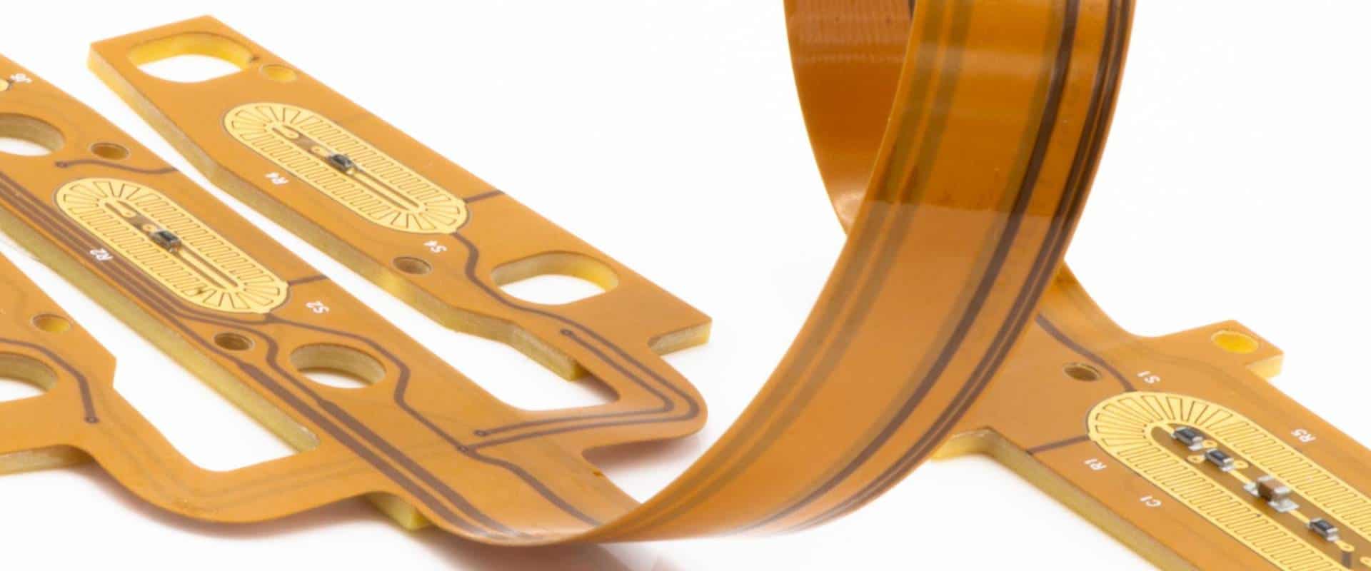
A flex circuit PCB is a printed circuit board that utilizes a flexible insulating dielectric substrate material such as polyimide or polyester. This allows the board itself to bend and flex while still providing electrical connections between components. The conductive traces are usually made of copper foil that has been laminated onto the flexible substrate. Components can be mounted directly to the flex PCB or connected via wires or cables.
Flex PCBs provide almost all of the same functions as rigid PCBs but with the added advantage of flexibility. Some key benefits of flex circuits include:
- Can conform to curved or irregularly shaped surfaces
- Dynamic flexing ability
- Thinner and lighter weight
- Improved high frequency performance
- Cost effective for lower volume productions
- Reliability in high vibration environments
These benefits make flex PCBs ideal for many applications where a rigid board would be inconvenient or impossible to use. Some common uses include:
- Consumer electronics – Cell phones, cameras, wearables
- Automotive – Sensors, control modules
- Medical – Hearing aids, imaging equipment
- Industrial – Robotics, instrumentation
- Military/Aerospace – Guidance systems, avionics
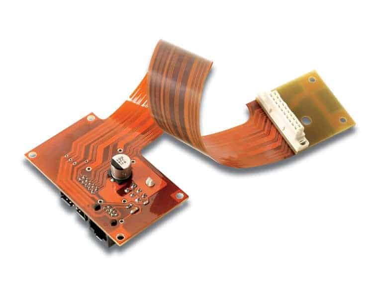
In many cases, flex PCBs are designed as partial or complete replacements for traditional wire harnesses. This can significantly reduce assembly time and points of failure. Next, we’ll look at how flex circuits achieve their flexibility.
Construction of Flex PCBs
While the circuitry design process is similar to rigid PCBs, the flexible construction of flex circuits provides unique fabrication and assembly considerations. Here are some key points on how flex PCBs are manufactured:
Substrate Materials
The most common substrates are polyimide (Kapton) and polyester (PET) films ranging from 1 to 5 mils (0.001 to 0.005 inches) thick. These provide the base layer that copper traces and other circuitry can be built up on. Polyimide offers high temperature and chemical resistance while PET provides an economical option.
Copper Traces
Copper foils, usually 1/2 to 2 oz in thickness, are laminated onto the substrate and then etched to form the conductive traces and pads. Flex PCBs typically use finer trace widths and spacing than rigid boards.
Coverlay/Coverfilm
A thin insulating coverlay or coverfilm layer is added over the top of the copper traces for protection and to prevent shorts. Additional stiffener layers may also be added to provide rigidity in certain areas.
Vias
Small plated through holes called microvias are used to connect layers and provide vertical interconnects in multilayer flex constructions. Blind or buried vias help optimize routing density.
Connectors
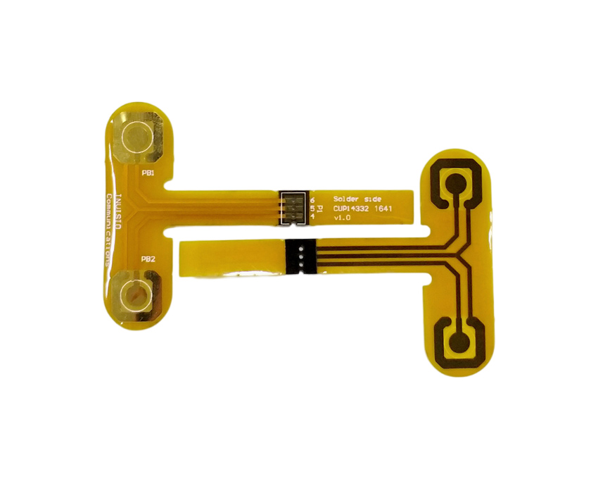
A variety of connector options are available for flex PCB interfaces including surface mount, sockets, card edge connectors, and cable connections. Conventional soldering can prove challenging so conductive epoxies are often used.
Assembly/Fabrication
Flex PCBs utilize many specialized assembly and fabrication processes. Cutting, stamping, etching, bonding and advanced imaging techniques produce tight tolerances and high reliability.
Understanding the unique construction methods of flex circuits helps illustrate why they provide advantages over rigid technology. Next we’ll highlight some specific applications that benefit from using flex PCBs.
Applications of Flexible Printed Circuit Boards
The flexible, lightweight, and durable nature of flex PCBs allows them to be used in a variety of innovative ways across many industries. Here are some examples:
Consumer Electronics
As consumer electronics like cell phones continue to get smaller, flex PCBs allow for flexible smartphone antennas, display connections, and wearable device circuitry. Flexible circuits are well suited for the dynamic rolling and folding required in these applications. They allow for lighter and thinner designs as well.
Automotive
Vehicles utilize flex PCBs in engine control units, lane departure warning systems, battery management systems, and steer-by-wire assemblies. Flex circuits are ideal for sensing systems and control modules where vibration resistance and high temperatures are necessary. Their dynamic flexing handles movement far better than rigid boards.
Medical
In medical devices like hearing aids or MRIs, flex circuits can wrap around complex contours while still providing critical connections. For disposable devices, flex PCBs offer a lower cost option. Their flexibility and improved signal integrity also aid medical imaging and diagnostic applications.
Industrial
Industrial robotics involve a lot of motion where rigid PCBs would easily crack or fail. Flex circuits can fold repeatedly while maintaining connections to sensors and controls. They also withstand dirt, liquids and other environmental factors common in industrial settings.
Military/Aerospace
Avionics, radars, guidance systems, and other aircraft electronics operate in high vibration environments where flex PCBs thrive. Their durability also suits the extreme temperatures and pressures of space applications. Flex circuits replace bulky wire harnesses in satellites, improving reliability and weight.
As you can see, flex PCBs deliver connectivity in situations where rigid technology just wouldn’t be feasible. The applications leveraging flexible circuit boards will continue expanding as new demands arise.
Flex PCB Design Considerations
Designing a successful flex PCB requires accounting for some unique considerations from both a circuit layout and mechanical perspective. Here are some important points to keep in mind:
- Dynamic Flexing – Avoid rigid components in high movement areas. Use stress relief features on traces.
- Minimum Bend Radii – Allow enough room for flexing without damaging traces. Polyimide can bend to 1mm typically.
- Layer Stackup – Staggering similar coefficient of thermal expansion (CTE) layers reduces stress.
- Routing – Optimize trace widths and spacing. Limit 90 degree turns.
- Vias – Use staggered microvias to transition layers. Filled and capped vias prevent cracking.
- Adhesives – Select durable, flexible adhesives for laminating layers.
- Connectors – Reinforce solder joints. Allow for misalignment. Prevent wicking.
- Stiffeners – Strategically place rigid sections to prevent twisting.
- Thermal Management – Flex PCBs can require creative solutions for heat dissipation.
With careful planning, flex PCBs can meet the demands of challenging applications that rigid boards simply cannot accommodate.
Pros and Cons of Flex Circuits
Like any technology, flex PCBs offer some clear advantages but also have limitations to consider. Here is a summary of the pros and cons:
Flex Circuit Benefits:
- Conforms to a variety of shapes and sizes
- Dynamic and repeated flexing ability
- Thin, lightweight, and compact
- Improved high frequency signal performance
- Vibration and impact resistant
- Eliminates complex wire harnesses
- Easily customized geometries
- Cost effective for lower volumes
Potential Drawbacks:
- More expensive for high volume production
- Limited in very high density or complex circuitry
- Can require additional shielding in some RF applications
- Repair and rework is more challenging
- Requires expert layout knowledge for reliability
- Minimal options for heat dissipation
Understanding this trade-off allows matching the right PCB technology to your application requirements. In many situations, the advantages clearly favor flex PCBs.
The Future of Flex Circuits
Flex PCBs have already become standard technology across a wide range of electronics, but expect that usage to increase as designers continue finding new applications for their distinct capabilities.
Some key trends that will shape flex PCB advancement:
- Enabling smaller wearable and portable electronics
- Higher density interconnects and finer traces
- Embedded passives and actives directly on flex
- Flex-rigid combinations for optimized designs
- Improved thermal management and dissipation
- Reduced costs expanding applications
With their reliable connectivity, dynamic flexing, and rugged durability, flex circuits deliver value across many demanding environments. As the technology and fabrication processes continue to evolve, flexible printed circuit boards will become accessible to more designers and reinvent electronics in new ways.
Frequently Asked Questions about Flexible PCBs
Here are answers to some common questions about flex circuit PCB technology:
What are some typical layer counts for flex PCBs?
Flex PCBs typically range from single layer to about 6 layers maximum. Rigid-flex combinations can have 8-12+ layers in the rigid sections. Higher layer counts are possible but can impact cost, yield, and reliability.
How small can flex circuit traces and spaces be?
Trace widths down to 0.10 mm (4 mils) are common. Spaces between traces can reach 0.075 mm (3 mils). Dimensions will vary based on manufacturer capabilities.
What types of connectors work best for flex PCB interfaces?
Surface mount connectors, card edge connectors, and cable-to-board solutions are most common. Sockets and plugs can also be used. Avoid connectors prone to misalignment or poor contact.
Can components be soldered directly onto flex PCBs?
SMT components can be directly soldered or glued to flex PCB surfaces, but thermal stress demands proper adhesive selection. Larger thru-hole parts should be avoided or isolated from dynamic flexing zones if possible.
How many flexing cycles can a flex circuit withstand?
Properly designed flex PCBs can endure hundreds of thousands to millions of flex cycles, far outlasting technologies like wire harnesses. This depends on trace/space geometries, materials, and bend radii.
Conclusion
As one of the fastest growing PCB technologies, flexible printed circuit boards enable electronics to be smaller, lighter, and more durable all while simplifying manufacturing and connectivity. With their distinct set of benefits and applications, flex circuits will continue transforming electronics across industries. By understanding the possibilities of flex PCBs, engineers can implement more advanced and reliable designs.


Leave a Reply