Introduction
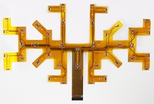
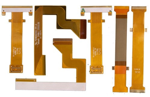
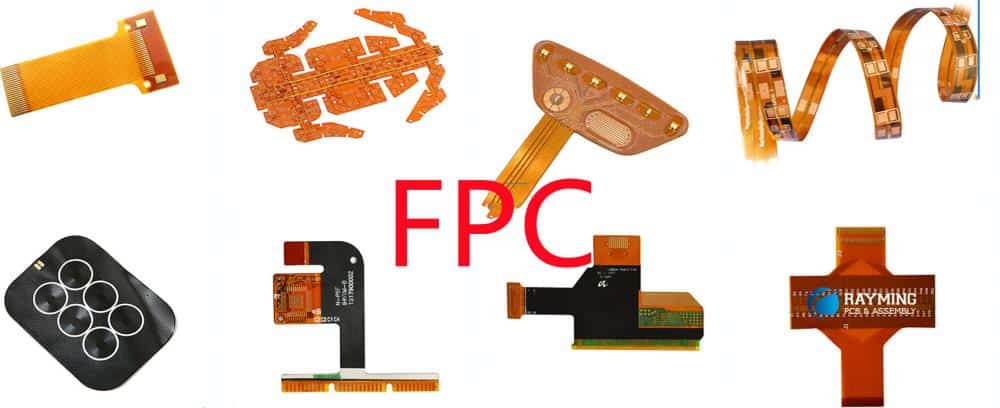
Flex circuits, also known as flexible printed circuits (FPCs), are a type of printable electronic interconnect component used to connect electronic devices. Flex circuits provide similar functionality to rigid printed circuit boards (PCBs) but have the ability to flex and bend. This flexibility allows them to be used in applications where rigid boards would be impractical. Some key advantages of flex circuits over rigid boards include:
- Ability to flex and conform to different shapes
- Lightweight and thin profile
- Can be folded and twisted without damage
- More durable under mechanical stress
- Allows for compact 3D packaging of electronics
Flex circuits are commonly manufactured from flexible dielectric materials like polyimide, polyester, polyethylene or PEEK using photolithographic processes adapted from rigid PCB fabrication. Polyimide films like Kapton or Upilex are most commonly used due to their excellent thermal stability and chemical resistance.
This article provides an overview of the materials, fabrication processes, assembly methods and applications for flex circuits.
Flex Circuit Materials
The basic construction of a flex circuit consists of a flexible dielectric substrate with conductive traces and components applied to it. The key materials used are:
Dielectric Substrates
- Polyimide films – Kapton, Upilex, Apical. Most common due to excellent flexibility, temperature resistance, chemical stability.
- Polyester films – PET, PEN. Lower cost but not as heat resistant as polyimide.
- Polyethylene – Flexible but limited temperature range.
- PEEK – Excellent thermal and chemical stability. More expensive.
- LCP – Liquid crystal polymer. Very heat resistant but more complex processing.
Conductors
- Copper – Most common conductor, can be rolled annealed or electrodeposited.
- Aluminum – Lower cost, not as conductive as copper. Mostly used for low frequency applications.
- Silver – Highest conductivity, but much higher cost than copper. Mostly used for high frequency or flexible displays.
Coverlayers and Bond Films
- Coverlayers – Provide electrical insulation and protect traces. Common materials include LCP, polyimide, acrylic.
- Bond films – Used to bond multiple layers of flex circuits together. Common materials are acrylic or modified polyimide.
Flex Circuit Fabrication Process
Flex circuits are fabricated using photolithographic processes adapted from rigid PCB fabrication. The basic steps are:
- Base Material Preparation – The flexible base dielectric material is cut to size and holes are punched.
- Conductor Patterning – Photoresist is applied and imaged to form a pattern mask. Conductors are then formed by etching or plating.
- Coverlayer Application – Additional layers of dielectric material are added as coverlayers over the conductors.
- Via Formation – Holes are drilled or laser cut to form conductive vias between layers. The vias are plated to form interconnections.
- Component Assembly – Components are placed and soldered onto the flex circuit. Connectors are added.
- Final Testing – Continuity, insulation resistance and functional testing is done.
Some key fabrication processes used in flex circuit production include:
Etching
In subtractive etching, a metal foil like copper is laminated onto the base substrate. Photoresist is then used to mask the desired conductor pattern. The exposed copper is etched away, leaving only the protected conductors.
Plating
In additive plating, a patterned photoresist mask is applied to a blank base substrate. Conductors are then electroplated onto the exposed areas of the substrate through the mask openings. After plating, the resist is stripped.
Laser Processing
Lasers are used for cutting flex circuit outlines, drilling microvias, ablating surfaces or selectively removing material. Excimer lasers are commonly used for processing polymer flex circuit materials.
Layer Bonding
Bonding films are used to adhere multiple layers of flex circuits together into multilayer configurations. Thermal, pressure and sometimes adhesive bonding processes are used.
Component Assembly
Surface mount components are applied with solder paste and reflow soldering. Connectors may be soldered or mechanically attached. Heat-sensitive components may require specialty conductive adhesives instead of soldering.
Flex Circuit Design Considerations
Key factors to consider in flex circuit design include:
- Bend radius – Avoid sharp folds that could fracture traces. Limit folds to at least 2-3x unfolded thickness.
- Conductor thickness – Thicker copper provides better conductivity and reduces losses. Minimum thickness is typically 0.5-1 oz (18-35 μm)
- Covercoat material – Must withstand handling, temperatures and chemicals expected in the application environment.
- Stiffener thickness – Added stiffeners may be needed to prevent flexing in certain areas.
- Layer count – More layers allows higher routing density. Typical range is 1- 30 conductive layers.
- High frequency design – Controlled impedance traces, minimized ground loops. May require microvias.
- Component selection – Prefer thin surface mount devices rated for flex applications. Avoid large or heavy through-hole parts.
Flex Circuit Applications
Some common product applications of flex circuit technology include:
- Mobile phones, tablets, laptops
- Computer peripherals (printers, disk drives, cameras)
- Automotive electronics
- Medical equipment
- Industrial and test instrumentation
- Wearable electronics
- Consumer products
- Aerospace and military systems
Flex circuits are valued in these applications for their ability to:
- Fit into tight, compact spaces
- Enable movement or articulation
- Withstand vibration and mechanical stresses
- Provide electrical connections through moving joints
- Allow for customized 3D packaging and cabling
Some examples of innovative flex circuit implementations:
Consumer Electronics
- Multi-layer rigid-flex boards in mobile phones with high density component mounting and interconnections.
- Flexible display interconnects in foldable phones, tablets and laptops.
- Flex cables for hinged clamshell designs and sliding/rotating connections.
Automotive
- Flex circuits in steering systems, engine compartments, doors and seats to withstand vibration and movement.
- Heater element circuits integrated into seat cushions and backrests.
- Antenna connections and circuits with ability to conform across curved surfaces.
Medical
- Imaging device flex interconnects providing dynamic cabling and multi-axis motion capabilities.
- Flex circuits integrated into wearable health monitors able to conform to body movement.
- Implants and insertable devices utilizing flexible circuits that can bend with natural motions.
aerospace/military
- Rugged flex cables for avionics systems exposed to vibration and wide temperature ranges.
- Lightweight flex circuitry allowing reduced weight versus cabling harnesses.
- Flex antenna arrays conforming to aircraft and missile surfaces.
Flex Circuit Assembly Techniques
In addition to surface mount assembly onto rigid sections of flex boards, specialized assembly and bonding methods are used to mount components onto flexible areas of circuits or interconnect rigid and flex sections:
Chip-on-Flex (COF)
Bare semiconductor die or chips are bonded directly onto flex circuit substrates using conductive adhesive or solder bumps. This provides a flexible equivalent of chip-on-board assembly.
Stretchable Circuits
Specialized elastic conductive materials and geometries allow circuits to stretch and deform well beyond normal flex capabilities. Enables applications like wearable biosensors.
Flex-Rigid Boards
Combine rigid FR4 PCB sections for component mounting with flexible polyimide sections for dynamic interconnections between rigid areas. Allows high component density and compact electronic packages.
Flexible Hybrid Electronics (FHE)
Integration of flex circuit interconnects with various surface mount components, sensors, surface mount chips, batteries, antennas, and other devices into thin, lightweight, bendable or conformal configurations.
Thermoform Interconnects
Flex circuits can be heated and formed into 3D shapes needed for unusual device packaging or enclosures using thermoforming processes with custom molds.
Here is an example comparison table outlining some key properties, advantages and disadvantages for common flex circuit substrate materials:
| Material | Key Properties | Advantages | Disadvantages |
|---|---|---|---|
| Polyimide (Kapton) | Excellent flexibility<br>High thermal stability<br>Chemical resistant | Most widely used<br>Withstands >300°C<br>Low moisture absorption | Relatively high cost<br>Limited stretchability |
| Polyester (PET) | Lower cost film substrate <br>Moderate thermal stability | Lower material cost <br>Easily laser ablated | Limited to 105°C temperature range<br>More moisture absorption than polyimide |
| Polyethylene (PE) | Very flexible<br>Lowest cost | Allows small bend radii<br>Lowest material cost | Limited to 80°C temperature range <br>Poor dimensional stability |
| Polyetheretherketone (PEEK) | Excellent thermal stability<br>Chemical and flame resistant | Withstands >240°C <br>Low moisture absorption | Very expensive <br>More difficult to laser ablate |
| Liquid Crystal Polymer (LCP) | Extremely high thermal stability | Withstands >280°C <br>Low CTE for reliable plating | Difficult processing <br>Higher material cost |
Flex Circuit Fabrication FAQ
What are some key considerations in designing a flex circuit?
Some important design factors are: controlling bend radius to avoid conductor fractures; minimizing unsupported spans of flexible areas; accounting for flex circuit thickness changes when folded; designing appropriate conductor widths and clearances for flexibility; and allowing for thermal expansion differences between metallization and polymer substrates.
What are some limitations of flex circuits compared to rigid PCBs?
Limitations include: fewer layers (typically under 30) versus over 100 layers for rigid boards; lower component densities; more limited in high frequency or high power applications; requires special component packaging to withstand flexing; tuning trace widths and spacing is critical; and cost is higher than rigid boards for low volume production.
What types of testing are performed on flex circuits?
Testing includes: visual inspection of circuits and solder joints; continuity testing for opens or shorts; insulation resistance testing; functional testing of circuits; flexure cycle testing by repeated folding/twisting; thermal cycling over the operating temperature range; and environmental testing like salt spray exposure or humidity testing.
How are components assembled onto flexible circuits?
Surface mount components are commonly attached using solder paste printing and reflow soldering, or with conductive epoxy for temperature sensitive components. Chips can be directly attached using flip chip or wire bonding. Connectors may be soldered or mechanically attached. Stiffeners may be required under some components.
How do flex circuits connect between stationary and moving sections?
Dynamic flex interconnects require specialized approaches like using flex-rigid boards with integrated rigid segments for mounting components; designing smooth curves in flex sections rather than sharp folds; incorporating periodic reverse bends; managing loads at transition points from flex to rigid areas. Stress relief features may be needed.


Leave a Reply