Introduction
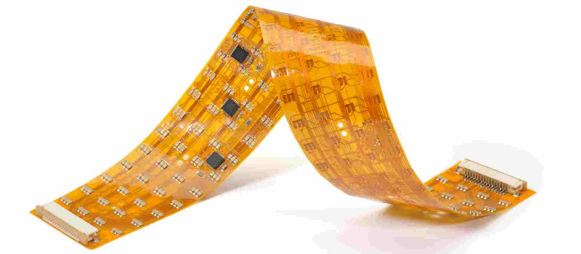
Flexible printed circuit boards (flex boards or flex circuits) have become an essential component in modern electronics due to their ability to bend and flex. Flex circuits allow circuitry to move freely and dynamically within a product. They are most commonly found in smaller consumer devices like cell phones, wearable tech, and medical devices where space is limited. However, flex boards are also utilized in larger products like industrial equipment, automobiles, and aerospace applications.
The unique properties of flex circuits provide several advantages over traditional rigid circuit boards:
- Ability to bend and shape to fit product enclosures
- Dynamic flexing and repeated motion capacity
- Lightweight and thin profile
- Effective in high vibration environments
- Increased reliability with fewer solder joints
- Design freedom and space optimization
But fabricating a reliable flex circuit requires specialized design and manufacturing techniques. This article will provide an overview of flex board construction, critical design factors, and advanced manufacturing processes involved in flex circuit production.
Flexible Circuit Board Construction
While flexible circuits can take many shapes and forms, they share some common design elements and materials. Here are the basic components of a typical flex board:
- Base Material – A thin, flexible plastic film forms the foundation. Polyimide is most commonly used due to its electrical insulation properties and high heat tolerance. Other base films like polyester or polyethylene are also options.
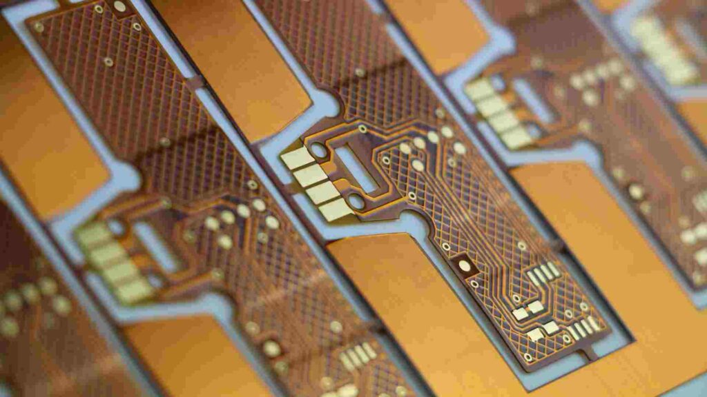
- Conductive Traces – Usually made from rolled annealed copper foil laminated onto the base. Trace thickness ranges from 1⁄4 oz (0.0007mm) to 2 oz (0.056mm) copper.
- Dielectric Layer – An insulating coverlay material overlays the conductive traces. Polyimide is most common but adhesive-coated polyesters are also used.
- Stiffeners – Frames or bars made from materials like aluminum or high-temp composites are added for structural support.
- Cover Coat – A thin overcoat layer is applied to protect traces from wear and environmental damage. Common options are liquid photoimageable solder masks, silicones, polyurethanes and epoxies.
- Terminations – Pads, lands or connectors are added so the flex circuit can interface with components or other circuit boards.
- Adhesives – Bond flex layers together. Acrylic or epoxy adhesives are typically used.
- Reinforcements – Extra material built up in high stress areas for mechanical strengthening. Done with additional laminate layers or screen printed dielectric.
Flex Circuit Design Considerations
Successfully designing a flex circuit requires accounting for the dynamic nature of flexible boards and their specialized construction. Here are some of the most important design factors:
Layer Stackup
The sequence of materials used in the flex circuit layers needs to be optimized based on a particular application’s requirements. Some key stackup considerations:
- Placing thicker, stronger materials toward the top and bottom of the layer sequence
- Locating low-modulus flexible layers like polyimide in the mid layers
- Embedding reinforcing cores or shields within the stackup
- Assigning dielectric materials according to their electrical performance specs
Conductor Layout
The conductor paths on a flex circuit experience more mechanical stress than on rigid boards. Optimization techniques include:
- Using wide traces and/or heavy copper weights for power circuits
- Minimizing unsupported span lengths over openings
- Building up thickness in high stress areas
- Utilizing crosshatching or serpentine patterns for redundancy
- Allowing adequate spacing between traces for isolation
Bend Radii
Careful control of flex circuit bend radiuses is critical to reliability. Key factors:
- Minimum bend radius varies based on stackup, copper weight, and Reinforcement
- Building enough cycles of flex life into bend areas
- Preventing acute bends near junctions between rigid and flex sections
Stiffener Integration
Proper structural stiffener placement provides support and facilitates handling:
- Locating stiffeners near connectors and along board edges
- Bridging internal cutouts and openings
- Applying selective spots of adhesive under stiffeners
- Extending stiffeners slightly beyond flex layers for clamping surface
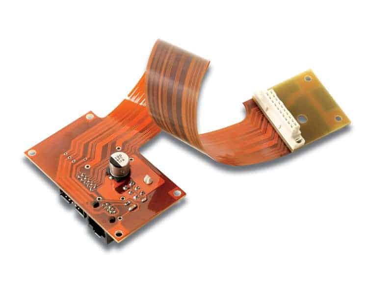
Board-to-Board Interconnects
Effective techniques for joining flex circuits to other boards include:
- Allowing adequate termination pad sizes for soldering, bonding or sockets
- Using standard flex-to-board connectors like FFCS or pogo pins
- Incorporating windows in stiffeners to access connection points
- Providing strain relief where flex circuits meet rigid boards
Robust Cover Coat
A protective top layer flex circuit cover coat is vital:
- Coverlay adds mechanical strength against cracks and tears
- Solder mask protects against environmental exposure and damage
- Screen printed or sprayed liquid coatings perform best
Advanced Flex Circuit FabricationProcesses
In addition to fundamental design practices, specialized manufacturing techniques enable fabrication of high reliability flex circuits.
Photolithographic Patterning
A photolithographic process transfers the conductor pattern onto the flexible board layers. This allows for precise trace dimensions and routings:
- Liquid or dry film photoresist is laminated onto copper clad dielectric
- The circuit image is exposed on the photoresist using UV light
- Photoresist is developed, removing unexposed areas
- Exposed copper is etched away, leaving circuit traces
Laser Processing
Lasers cut, drill, or ablate material away with extreme precision. Laser processing is used to:
- Cut flex circuit patterns with accuracy up to +/- 0.001”
- Drill extremely small and tightly spaced holes through multilayer boards
- Ablate away selective areas of coatings for high density patterning
Layer-to-Layer Registration
Precisely aligning flex circuit layers is critical for reliable interconnects between layers. Registration processes include:
- Tooling pin alignment systems
- Optical scanning for pattern matching between layers
- Laser or mechanical drilling of tooling holes
Surface Finishes
Applying special coatings enhances flex circuit functionality:
- Electroless nickel/immersion gold (ENIG) for robust solderability
- Electropated gold increases corrosion resistance
- Solder reflow-compatible organic surface preservatives (OSPs)
Flex-to-Rigid Manufacturing
Combining rigid and flex materials in one circuit requires specialized fabrication:
- Sequential circuits – rigid layers made first, then flex added
- Concurrent processing – rigid and flex done together
- Cutouts in rigid sections allow flexing – made with routing, punching or lasers
Automated Handling and Assembly
Production scale flex circuit manufacturing relies on automation:
- Reel-to-reel material handling systems
- Robotic loading/unloading of circuit boards
- Automated optical inspection and testing
- Computer-controlled pick-and-place assembly
With attention to design considerations and use of advanced manufacturing techniques, reliable and robust flexible printed circuit boards can be fabricated. The unique adaptability of flex circuits enables innovative electronics packaging not feasible with rigid boards alone. Continued development of flex PCB technology will allow their advantages to be utilized across even more diverse applications.
Frequently Asked Questions
What are some key differences when designing a flex circuit versus a rigid printed circuit board?
Some of the main design differences include:
- Accounting for dynamic and repeated flexing motions
- Managing stresses around bends with specialized trace layouts
- Minimizing unsupported spans across gaps or cutouts
- Allowing for stretching and contraction of the flexible substrate
- Optimizing layer stackups for bendability
- Incorporating only flex-compatible components
What types of products commonly use flex circuits?
Flexible printed circuits are found in many consumer and commercial products including:
- Mobile consumer electronics – Cell phones, tablets, wearables
- Computer/storage devices – Laptops, hard drives, printers
- Automotive applications – Sensors, control circuits, LED lighting
- Medical devices – Hearing aids, imaging equipment, monitors
- Aerospace/defense – Avionics, guidance systems, engine controls
How are components assembled onto flex circuits?
Common flex circuit assembly techniques include:
- SMT assembly – Surface mount components added with solder paste and reflow
- Conductor gluing – Components fixed using conductive epoxies or films
- Crimping – Terminals mechanically crimped onto pad/land interfaces
- Press-fit – Component leads press inserted into plated through holes
- Stapling – Component leads bent and stapled to pads
What are some key challenges in flex circuit fabrication?
Some of the main flex circuit fabrication challenges involve:
- Achieving fine trace geometries and tight tolerances
- Aligning layers with high registration accuracy
- Producing high mix, low volume designs
- Preventing damage or distortion of thin flexible materials
- Optimizing processes for new exotic substrate materials
- Handling difficulties due to lack of rigidity
How are multi-layer flex circuits constructed?
Buildup processes for multi-layer flex boards include:
- Sequential bonding – Additional flex layers laminated using adhesive
- Buildup processing – Trace layers added with electroplating
- Mixed – Combination of additional laminations and plated traces
- Rigid-flex – Sections of rigid fiberglass bonded to flex layers
The specialized properties and capabilities of flexible printed circuit boards will ensure they continue growing as a key enabling technology across electronics industries. Continued advancements in flex design, materials, and manufacturing will allow flex circuits to become even more sophisticated and widespread in the future.


Leave a Reply