What is the DS1307?
The DS1307 is a low-power, full binary-coded decimal (BCD) clock/calendar plus 56 bytes of NV SRAM. It communicates via an I2C interface and requires minimal external components, making it an ideal solution for embedded systems and other applications that require accurate timekeeping.
Key Features of the DS1307
- Real-time clock (RTC) counts seconds, minutes, hours, date of the month, month, day of the week, and year with leap-year compensation valid up to 2100
- 56-byte, battery-backed, non-volatile (NV) RAM for data storage
- I2C serial interface
- Programmable square-wave output signal
- Automatic power-fail detect and switch circuitry
- Consumes less than 500nA in battery backup mode with oscillator running

DS1307 Pinout
The DS1307 comes in an 8-pin DIP (Dual Inline Package) or an 8-pin SOIC (Small Outline Integrated Circuit) package. The pinout for both packages is as follows:
| Pin | Symbol | Function |
|---|---|---|
| 1 | X1 | 32.768kHz Crystal Connection |
| 2 | X2 | 32.768kHz Crystal Connection |
| 3 | VBAT | +3V Battery Input |
| 4 | GND | Ground |
| 5 | SDA | Serial Data Input/Output |
| 6 | SCL | Serial Clock Input |
| 7 | SQW/OUT | Square Wave/Output Driver |
| 8 | VCC | +5V Power Supply |
Crystal Connections (X1 and X2)
The DS1307 requires a 32.768kHz crystal to be connected between the X1 and X2 pins for accurate timekeeping. The crystal should have a load capacitance of 12.5pF. Two external load capacitors (C1 and C2) are also required, typically with a value of 22pF each.
Battery Input (VBAT)
The VBAT pin is used to connect a 3V backup battery to the DS1307. This battery maintains the clock and RAM contents when the main power supply is absent. A diode should be placed between the battery and the VBAT pin to prevent charging the battery when the main power supply is active.
Ground (GND) and Power Supply (VCC)
The GND pin should be connected to the ground of the system, while the VCC pin should be connected to a stable +5V power supply.
Serial Data and Clock (SDA and SCL)
The DS1307 communicates via an I2C interface, which uses the SDA (Serial Data) and SCL (Serial Clock) pins. These pins should be connected to the corresponding pins on the microcontroller or other I2C master device. Pull-up resistors are required on both lines, typically with values between 1.8kΩ and 10kΩ.
Square Wave/Output Driver (SQW/OUT)
The SQW/OUT pin can be programmed to output a square wave signal with one of four frequencies: 1Hz, 4kHz, 8kHz, or 32kHz. This signal can be used for various purposes, such as generating interrupts or providing a clock signal for other devices. If not used, this pin can be left unconnected.

Interfacing the DS1307 with a Microcontroller
To interface the DS1307 with a microcontroller, follow these steps:
- Connect the VCC and GND pins to the appropriate power supply and ground connections on the microcontroller.
- Connect the SDA and SCL pins to the corresponding I2C pins on the microcontroller. Ensure that pull-up resistors are present on both lines.
- If using the square wave output, connect the SQW/OUT pin to the desired input pin on the microcontroller.
- Connect the 32.768kHz crystal and load capacitors between the X1 and X2 pins.
- If using the battery backup feature, connect a 3V battery to the VBAT pin through a diode.
Here’s a simple schematic showing the connections between a DS1307 and an Arduino Uno:
        DS1307              Arduino Uno
        ------              -----------
   VCC  - 5V               - 5V
   SDA  - SDA              - A4 (SDA)
   SCL  - SCL              - A5 (SCL)
   SQW  -                  -
  VBAT  - 3V Battery + Diode
   GND  - GND              - GND
    X1  - 32.768kHz Crystal
    X2  - 32.768kHz Crystal

Programming the DS1307
To program the DS1307, you’ll need to use the appropriate libraries for your microcontroller. For Arduino, the RTClib library is a popular choice. This library provides easy-to-use functions for setting and reading the time and date from the DS1307.
Here’s a simple Arduino sketch that demonstrates how to set and read the time using the DS1307:
#include <Wire.h>
#include "RTClib.h"

RTC_DS1307 rtc;

void setup () {
  Serial.begin(9600);

  if (! rtc.begin()) {
    Serial.println("Couldn't find RTC");
    while (1);
  }

  // Set the time (uncomment the following line and adjust the date and time as needed)
  // rtc.adjust(DateTime(2023, 4, 15, 10, 30, 0));
}

void loop () {
  DateTime now = rtc.now();

  Serial.print(now.year(), DEC);
  Serial.print('/');
  Serial.print(now.month(), DEC);
  Serial.print('/');
  Serial.print(now.day(), DEC);
  Serial.print(' ');
  Serial.print(now.hour(), DEC);
  Serial.print(':');
  Serial.print(now.minute(), DEC);
  Serial.print(':');
  Serial.print(now.second(), DEC);
  Serial.println();

  delay(1000);
}
This sketch does the following:
- Includes the necessary libraries (
Wire.handRTClib.h). - Creates an instance of the RTC_DS1307 class called
rtc. - In the
setup()function: - Initializes serial communication.
- Initializes the RTC and checks if it was found.
- (Optional) Sets the initial time and date using the
rtc.adjust()function. - In the
loop()function: - Retrieves the current date and time using the
rtc.now()function. - Prints the date and time to the serial monitor.
- Delays for one second before repeating the loop.
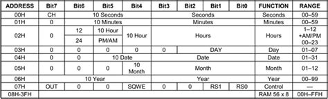
DS1307 Register Map
The DS1307 has several registers that can be accessed via the I2C interface to control its various functions. The most important registers are:
| Address | Register |
|---|---|
| 0x00 | Seconds |
| 0x01 | Minutes |
| 0x02 | Hours |
| 0x03 | Day of the Week |
| 0x04 | Date |
| 0x05 | Month |
| 0x06 | Year |
| 0x07 | Control |
| 0x08-0x3F | RAM |
The first seven registers (0x00 to 0x06) store the current time and date in BCD format. The control register (0x07) is used to configure the square wave output and to enable or disable the oscillator. The remaining 56 bytes (0x08 to 0x3F) are available as battery-backed RAM for storing user data.
Troubleshooting Common Issues
If you encounter problems while using the DS1307, consider the following:
- Double-check all connections, especially the power supply and I2C lines.
- Ensure that the crystal is connected correctly and that the load capacitors have the correct values.
- Verify that the backup battery is properly connected and has sufficient charge.
- Check that the I2C address of the DS1307 matches the address used in your code (the default address is 0x68).
- Make sure that you are using the correct libraries and that they are up to date.
If you still experience issues, consult the DS1307 datasheet or seek assistance from the Arduino community or other relevant forums.
Frequently Asked Questions (FAQ)
-
Q: Can I use a different crystal frequency with the DS1307?
A: No, the DS1307 is designed to work specifically with a 32.768kHz crystal. Using a different frequency will result in inaccurate timekeeping. -
Q: How long can the DS1307 keep time without a power supply?
A: With a fully charged backup battery, the DS1307 can maintain accurate timekeeping for several years. -
Q: Can I use the DS1307 with a 3.3V microcontroller?
A: Yes, the DS1307 is compatible with both 3.3V and 5V microcontrollers. However, you should ensure that the I2C pull-up resistors are appropriate for the voltage level used. -
Q: How accurate is the DS1307?
A: The accuracy of the DS1307 depends on the accuracy of the 32.768kHz crystal used. With a typical crystal, the DS1307 can maintain an accuracy of ±2ppm, which equates to about ±1 minute per year. -
Q: Can I use the battery-backed RAM in the DS1307 to store data?
A: Yes, the DS1307 provides 56 bytes of battery-backed RAM that can be used to store user data. This data will be retained even when the main power supply is removed, as long as the backup battery is connected and has sufficient charge.
Conclusion
The DS1307 is a versatile and easy-to-use real-time clock IC that can be easily integrated into various projects requiring accurate timekeeping. By understanding its pinout, features, and how to interface it with a microcontroller, you can quickly incorporate the DS1307 into your designs and take advantage of its reliable timekeeping capabilities.


Leave a Reply