Introduction to PCB Drilling
Printed Circuit Board (PCB) drilling is a crucial step in the manufacturing process of electronic devices. It involves creating precise holes in the PCB to allow for the insertion of components and the creation of electrical connections. The accuracy and quality of the drilling process can have a significant impact on the overall functionality and reliability of the final product.
Types of PCB Drilling
There are two main types of PCB drilling:
-
Mechanical Drilling: This method uses a drill bit to physically create holes in the PCB. It is the most common method used for PCB drilling.
-
Laser Drilling: This method uses a laser to burn holes into the PCB. It is typically used for smaller, more precise holes that are difficult to achieve with mechanical drilling.
PCB Drilling Equipment
Drill Bits
Drill bits are the most essential component of PCB drilling equipment. They come in various sizes and materials, depending on the specific requirements of the project.
| Material | Description | Advantages | Disadvantages |
|---|---|---|---|
| Carbide | Made from tungsten carbide, a hard and durable material | Long lifespan, suitable for high-volume production | Expensive, brittle |
| High-Speed Steel (HSS) | Made from high-speed steel, a tough and heat-resistant material | Less expensive than carbide, suitable for low-volume production | Shorter lifespan compared to carbide |
| Diamond-Coated | Coated with a layer of diamond particles | Extremely hard and wear-resistant, suitable for drilling hard materials | Very expensive, limited applications |
Drilling Machines
There are several types of drilling machines used for PCB drilling:
-
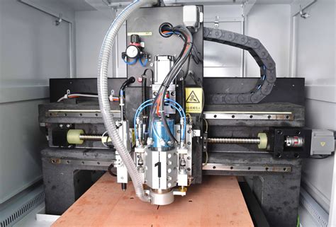
CNC Drilling Machine: Computer Numerical Control (CNC) drilling machines are automated machines that use computer software to control the drilling process. They offer high precision and repeatability, making them suitable for high-volume production.
-
Manual Drilling Machine: Manual drilling machines are operated by hand and require a skilled operator. They are typically used for low-volume production or prototyping.
-
Laser Drilling Machine: Laser drilling machines use a laser to create holes in the PCB. They offer high precision and are suitable for creating small, intricate holes.

PCB Drilling Process
Step 1: PCB Design
The first step in the PCB drilling process is to design the PCB using computer-aided design (CAD) software. The design includes the placement of components, electrical connections, and the location and size of the holes to be drilled.
Step 2: Drill File Generation
Once the PCB design is complete, a drill file is generated. The drill file contains information about the location, size, and quantity of holes to be drilled in the PCB.
Step 3: Drilling
The PCB is then placed in the drilling machine, and the drilling process begins. The machine reads the drill file and creates the holes in the specified locations and sizes.
Step 4: Deburring
After drilling, the PCB is inspected for any burrs or rough edges around the holes. These can be removed using a deburring tool or by running the PCB through a chemical deburring process.
Step 5: Cleaning
Finally, the PCB is cleaned to remove any debris or contaminants that may have accumulated during the drilling process. This is typically done using a specialized cleaning solution and ultrasonic cleaning equipment.

Factors Affecting PCB Drilling Quality
Several factors can affect the quality of PCB drilling:
-
Drill Bit Quality: The quality and condition of the drill bit can have a significant impact on the accuracy and consistency of the holes.
-
Machine Calibration: The drilling machine must be properly calibrated to ensure accurate hole placement and size.
-
Spindle Speed: The speed at which the drill bit rotates can affect the quality of the holes. Higher speeds may cause the drill bit to wear out faster or create rough edges around the holes.
-
Feed Rate: The feed rate, or the speed at which the drill bit moves through the PCB, can also affect hole quality. A feed rate that is too high may cause the drill bit to break or create inconsistent holes.

Common PCB Drilling Defects
Several common defects can occur during the PCB drilling process:
-
Misaligned Holes: Holes that are not drilled in the correct location can cause issues with component placement and electrical connections.
-
Oversized or Undersized Holes: Holes that are too large or too small can cause issues with component fit and electrical continuity.
-
Rough Hole Edges: Rough edges around the holes can cause issues with component placement and solderability.
-
Drill Breakage: Drill bits can break during the drilling process, leaving debris in the holes or causing damage to the PCB.
Best Practices for PCB Drilling
To ensure high-quality PCB drilling, follow these best practices:
-
Use High-Quality Drill Bits: Invest in high-quality drill bits that are appropriate for the specific requirements of your project.
-
Regularly Maintain and Calibrate Equipment: Regular maintenance and calibration of drilling equipment can help ensure consistent hole quality and prevent defects.
-
Optimize Spindle Speed and Feed Rate: Experiment with different spindle speeds and feed rates to find the optimal settings for your specific application.
-
Implement Quality Control Measures: Implement quality control measures, such as visual inspection and electrical testing, to identify and address any defects early in the process.
Conclusion
PCB drilling is a critical step in the manufacturing process of electronic devices. By understanding the different types of drilling equipment, the drilling process, and the factors that affect hole quality, manufacturers can optimize their drilling operations to produce high-quality PCBs with consistent and reliable electrical connections.
Frequently Asked Questions (FAQ)
-
What is the difference between mechanical and laser drilling for PCBs?
Mechanical drilling uses a physical drill bit to create holes in the PCB, while laser drilling uses a laser to burn holes into the PCB. Laser drilling is typically used for smaller, more precise holes that are difficult to achieve with mechanical drilling. -
How do I choose the right drill bit for my PCB drilling application?
The choice of drill bit depends on several factors, including the material of the PCB, the size and quantity of holes, and the desired hole quality. Carbide drill bits are suitable for high-volume production, while HSS drill bits are less expensive and suitable for low-volume production. -
What causes misaligned holes in PCBs?
Misaligned holes can be caused by several factors, including improper machine calibration, drill bit wear or breakage, or incorrect drill file generation. -
How can I prevent drill bit breakage during PCB drilling?
To prevent drill bit breakage, use high-quality drill bits that are appropriate for the specific requirements of your project, regularly maintain and calibrate your drilling equipment, and optimize spindle speed and feed rate settings. -
What are some common quality control measures for PCB drilling?
Common quality control measures for PCB drilling include visual inspection of holes for size, location, and edge quality, as well as electrical testing to ensure proper electrical continuity and functionality of the final product.


Leave a Reply