Introduction
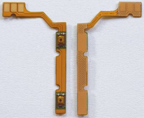
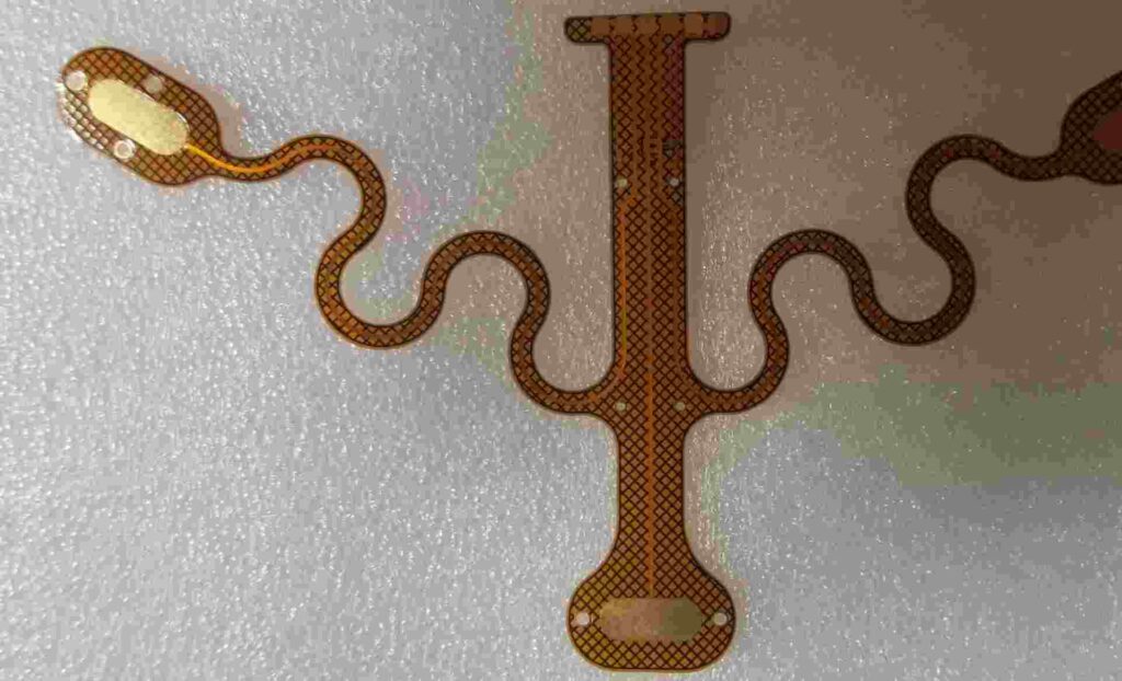
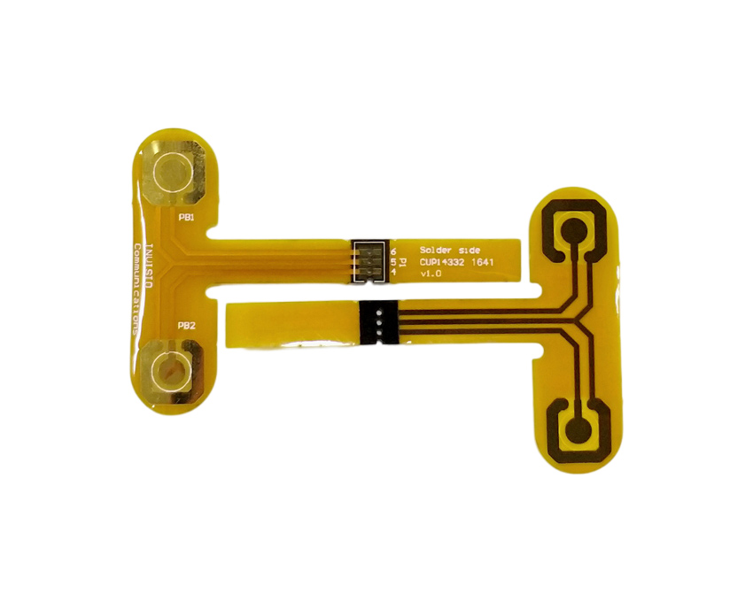
Flexible printed circuit boards (flex PCBs or flex circuits) are a type of PCB that can bend and flex. They are made from flexible insulating substrate materials like polyimide or PET instead of traditional rigid FR-4. Flex PCBs are extremely useful when designing electronics that need to move dynamically or fit into tight spaces.
Making your own DIY flex PCBs at home is totally doable with the right materials and techniques. This comprehensive guide will walk you through the entire flex PCB creation process step-by-step. Read on to learn how to design, pattern, etch, assemble, and finish your own professional-quality flex circuits all in your home workshop or makerspace.
Materials Needed for DIY Flex PCBs

To make DIY flex PCBs at home, you’ll need the following materials and tools:
- Flexible Substrate – Polyimide (Kapton) or PET film in the desired thickness. Good sources are FlexPCB.com or Amazon.
- Copper Foil – 1 or 2 oz rolled copper foil, also available from FlexPCB or Amazon.
- Etchant – Ferric chloride or ammonium persulfate. Ferric chloride is easier to find.
- Transfer Paper – Special PCB transfer paper like those from Sunstone Circuits.
- Etching Tank – A plastic tub or tray to hold the etchant solution during etching.
- Etching Tools – Tweezers, chopsticks, etc. to move boards during etching.
- Soldering Iron & Solder – For assembling components onto the finished flex PCB.
- Multimeter – Helpful for testing traces and confirming isolations.
- Safety Gear – Gloves, goggles, apron. Etchant solutions are corrosive.
That covers the essentials. Nice-to-have extras include a laser printer for transfers, a laminator, flux, Kapton tape, and more.
Software for Designing Flex PCBs
To design the circuit layouts for your DIY flex PCBs, you’ll need PCB design software. Here are some good options:
- Eagle – The free version of Autodesk Eagle is a very popular PCB design tool. It has a bit of a learning curve but works great once you get the hang of it.
- KiCad – KiCad is a free, open-source PCB design suite that runs on Windows, Mac, and Linux. It’s very capable software.
- DipTrace – DipTrace has a free version with a 2-layer board size limit, but is still useful for simple flex PCB projects.
- Inkscape – Inkscape is free vector graphics software that can be used to design basic flex PCB layouts and traces.
Any of the above programs will do the job. Eagle or KiCad may have a steeper initial learning curve but offer more features for advanced designs.
Step-by-Step Process for DIY Flex PCBs
Once you have all the necessary supplies and software, you’re ready to start creating your own flex PCBs. Here is the step-by-step process:
1. Design the Flex PCB Layout
- Create a new project in your PCB design software. For single-sided boards, only a top copper layer is needed.
- Arrange components and route traces on the top layer, keeping in mind the flexible nature of the PCB. Avoid arcs and acute angles.
- Use teardrop pads and generous trace widths for durability. Minimize crossing traces.
- Add silkscreen layer markings, board outline, and any other necessary layers.
- Print or export the design as a high-resolution image file.
2. Prepare the Flexible Substrate
- Cut a piece of Kapton or PET substrate to size using scissors. Wear gloves to prevent oils from contaminating the surface.
- Clean the substrate thoroughly with isopropyl alcohol. This improves toner adhesion.
3. Transfer the PCB Layout
- Print the layout onto the transfer paper using a laser printer or photocopier. Toner sticks better than inkjet prints.
- Sandwich the printed transfer paper and substrate between sheets of paper and run them through a laminator heated to around 300°F. This transfers the toner firmly onto the flex substrate. Alternatively, you can use an iron but must take care to apply even pressure.
- Soak the board in water to dissolve the transfer paper, leaving just the toner on the substrate. Dry thoroughly before moving to the next step.
4. Etch the Copper
- Cut a piece of copper foil slightly larger than the PCB substrate. Remove any backing and press the foil onto the toner, forming a tight bond.
- Prepare the ferric chloride or other etchant solution in a plastic tub or tray. Always add acid to water slowly.
- Submerge the copper-clad board in the etching solution. Agitate frequently and watch closely to avoid under- or over-etching. The copper not protected by toner will be dissolved, leaving just the desired traces and features.
- Rinse thoroughly with water and dry when the etching is complete.
5. Solder Components
- Populate the PCB by soldering components onto the pads and traces. Use a low temperature iron and fine solder. Take care not to melt the substrate itself.
- Avoid placing components in areas that will need to bend or flex. Reinforce with Kapton tape as needed.
- Clean off flux residue when done soldering using isopropyl alcohol and a toothbrush.
6. Assemble and Protect
- If needed, connect multiple rigid and flexible PCB sections using adhesive or board-to-board connectors.
- Fold or shape the flex PCB into its final configuration and secure with adhesive standoffs. Avoid tight folds that could fracture traces.
- Protect exposed traces from shorting using insulating tape or conformal coatings.
And that covers the essential process of designing, prototyping, and assembling DIY flexible PCBs at home! With the right materials it’s straightforward to create custom flex circuits for your electronics projects.
Tips for Successfully Making DIY Flex Circuits

Here are some handy tips and best practices to employ when fabricating your own flex PCBs:
- Use a laser printer or photocopier, not inkjet. Laser toner adheres much better to the substrate.
- Keep the transfer paper dry. Moisture will prevent the toner from sticking.
- Let the newly etched PCB sit for a day before handling to allow the traces to fully set.
- Go slowly and gently when soldering. The flex substrate can melt. Use low heat.
- Only fold where necessary, and avoid tight folds. Use large bend radii.
- Consider reinforcing high-stress points with Kapton tape or conformal coating.
- Watch for “bridging” where traces cross. Insulate with tape if shorting occurs.
- Double check for any stray bits of copper causing unwanted connections.
Following these tips will help you successfully create durable, professional-quality flex PCBs without any manufacturing equipment!
Example DIY Flex PCB Projects
Looking for inspiration for your own flex PCB designs? Here are some example projects you can create at home:
Wearable LED Display
Programmable flex circuits with mounted LEDs are perfect for wearable displays like clothing, nametags, or armbands. Use a microcontroller to control the display.
Flex Sensor
Printed flex sensors change resistance when bent. Pair with an Arduino to create bend-sensitive controls for robotics or musical instruments.
Adaptable Robot Limbs
Flexible robot limb segments let arms and grippers bend and move more naturally. Use rigid PCBs for controllers, with flex sections for the joints.
Curved LED Light Panels
Mount LED strips and drivers onto a thin flexible substrate to create cool curved accent lighting effects for homes or events.
Foldable Quadcopter Arms
Give quadcopter frame arms flexibility. They can fold up when not flying and bend slightly to absorb crashes and impacts.
The applications for DIY flex PCBs are limitless! Building your own gives you the freedom to create exactly the flex circuit you need.
Frequently Asked Questions
Here are answers to some common questions about making DIY flexible PCBs:
What thickness of copper foil should I use?
1 oz copper foil (35 μm) is a good standard thickness for DIY flex PCBs. 2 oz (70 μm) can be used for more durable circuits.
What’re some good substrate materials besides Kapton?
PET film, fabric, and some plastics like ABS can be used. Kapton remains the most common and reliable flex substrate though.
How tightly can a flex PCB be bent?
Avoid bend radii smaller than 5 times the total thickness for repeated flexing. For sharp folds allow 10x thickness. Reinforce tight bends if needed.
Can I solder components onto both sides of the PCB?
Yes, you can create double-sided flex PCBs with careful alignment. But for DIY, single-sided is much easier to fabricate.
What trace width and spacing should I use?
For handmade boards, 0.2mm traces with 0.2mm spacing is reasonable. Wider traces and spacing improves reliability.
Conclusion
DIY flexible printed circuit boards enable you to create flex PCBs customized exactly for your project needs. While the fabrication process requires care and precision, the ability to prototype and produce flex circuits at home dramatically speeds up development time compared to outsourcing fabrication.
This guide covered the necessary equipment, materials, software, step-by-step instructions, design tips, example projects, and helpful FAQs needed to successfully build your own flexible PCBs. The basic process combines printed circuit board fabrication techniques with the use of flexible substrate materials like Kapton. Armed with this knowledge, you can now fabricate simple or complex flex circuits all on your own. Enjoy the benefits of rapid in-house prototyping as you design ingenious projects and gadgets relying on flexible electronics!


Leave a Reply