Introduction
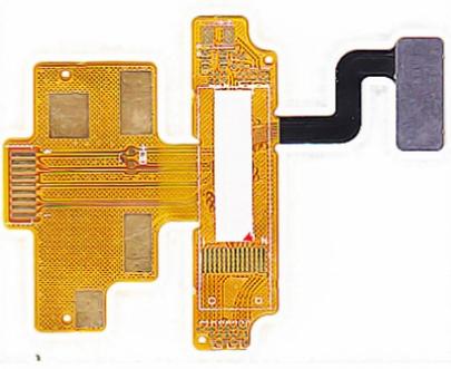
Flexible printed circuit boards (FPCBs) are a type of printed circuit board that can bend and flex. Unlike traditional rigid circuit boards, FPCBs allow circuits to move and twist along with other components they are attached to. This makes them perfect for use in things like wearable devices, folding screens, robotics, and other applications where movement and flexibility are needed.
Building your own FPCBs can be a fun DIY electronics project. With some basic skills, tools, and materials, you can create custom flex circuits for prototyping or small production runs. This guide will walk through the basics of how to design and assemble your own DIY flex PCBs.
Design Considerations for DIY Flex Circuits
When planning your flex PCB project, there are some important factors to consider during the design process:
Circuit Layout
- Trace widths and spacing – Traces need to be larger than on rigid boards due to flexing. Aim for at least 6 mil width and spacing.
- Avoid 90 degree angles – Use curved traces instead to prevent traces from cracking.
- Stiffener areas – Add reinforced islands where components will mount.
- Fold lines – Plan where the board will bend and arrange traces accordingly.
Substrate Material
- Thickness – 1 to 5 mils is common. Thinner material allows tighter bending.
- Layer stackup – Double-sided flex, multilayer, or rigid-flex are options.
- Polyimide films like Kapton are most commonly used.
Components
- Use small surface mount devices – Avoid bulky through-hole components.
- Adhesives – Use flexible adhesives like silicone to attach components.
- Allow for flex and movement – Give space for components to bend.
Connectors
- FPC connectors allow easy mating with other boards.
- Avoid rigid connectors that impede flexing.
By considering these factors early when laying out your flex board, you can avoid potential issues down the road.
Making Your Own Flex PCBs
Once you have your circuit designed, here is an overview of the steps involved in creating DIY flex PCBs:
1. Print the Circuit Pattern
- Create the board layout in CAD software like Eagle, KiCad, etc.
- Print the copper layer traces onto a toner transfer sheet. An inkjet printer also works.
- Ensure traces are thick enough to transfer well.
2. Prepare the Substrate
- Clean the Kapton or other flexible substrate material.
- Optional: Apply liquid solder mask to any areas you want to remain uncovered. Let cure.
3. Transfer the Toner
- Place the printed toner transfer sheet onto the substrate, with the toner side down.
- Use a hot laminator or clothes iron to heat transfer the toner onto the substrate.
4. Etch Away Exposed Copper
- Soak in etchant solution like ferric chloride to eat away unwanted copper.
- Clean off any toner residue with acetone.
5. Drill Holes for Vias
- Mark component leads and via hole locations.
- Carefully drill holes with a small bit in a drill press.
6. Add Copper Finish
- Electroless copper plating solution coats exposed copper traces.
- Alternatively use copper foil and conductive epoxy.
7. Solder Components
- Attach any flexible surface mount components with solder.
- Apply adhesive underneath prior to soldering.
With those main steps complete, you now have a finished DIY flex PCB! Be sure to test continuity and functionality before installing it into your project.
Tips for Successfully Building Flexible Boards
Here are some helpful tips for getting the best results when fabricating your own flex circuits:
- Use a high resolution laser printer for best toner transfer.
- Apply even pressure and heat when transferring toner.
- Double check no traces are bridged or damaged before etching.
- Use extra care when drilling to avoid tearing substrate.
- Work slowly and carefully when soldering flexible boards.
- Consider reinforcements like stiffeners at component sites.
- Test continuity before and after bending and flexing the board.
- Start with a simple single or double sided board for your first build.
Taking it slow and being meticulous in your fabrication process will help ensure your DIY flex PCB comes out functioning properly. Don’t be afraid to scrap and remake boards that don’t pass testing. With practice, you’ll be able to produce robust flex circuits of your own design.
Applications for DIY Flexible PCBs
Some cool example projects you can create with homemade flex PCBs:
- Wearable circuit boards for connected clothing and accessories.
- Circuits that integrate with moving mechanical parts.
- Robotic sensor appendages and limbs.
- Unique interactive art pieces.
- Foldable/rollable display boards.
- Conformable health monitoring devices.
- Flexible lighting arrays and EL wire projects.
- Dynamic exhibit props and displays.
Really any application where you want or need integrated circuits that can bend, twist, or drape comfortably is a perfect opportunity to use flex PCBs. Prototypes and one-off boards are also easier to produce than trying to source small quantity custom flex PCBs from a traditional manufacturer.
So explore the possibilities and let your imagination run wild when designing your own flexible printed circuit boards!
Frequently Asked Questions
Here are some common questions about creating DIY flex PCBs:
What materials do I need?
You’ll need a flexible substrate like Kapton polyimide film, a toner transfer method such as a laser printer or inkjet and transfer paper, etchant, drill bits, copper plating solution, solder, adhesives, and components.
Is heat required for transferring the toner?
Yes, you need heat from either a hot laminator, clothes iron, or a product specifically made for toner transfer like the LPKF Protomat. Heat helps soften the toner so it adheres to the substrate.
Can I make multilayer flex PCBs?
It’s possible but requires special preparation of the flexible substrate to bond multiple layers together. Single or double sided boards are recommended for DIY work.
What’s the minimum bend radius for flex circuits?
It depends on the thickness, but a common rule is no tighter than 10 times the total board thickness for dynamic flexing. Allow generous radii where possible.
How do I connect components if I can’t solder through holes?
Use surface mount parts and conductive epoxy or specialized flex component adhesives. SMT pads can also be soldered as usual.
Conclusion
Designing and fabricating your own flexible PCBs is very achievable using the toner transfer method and basic DIY electronics skills and tools. With smart layout considerations and carefully following fabrication steps, you can produce durable flex circuits for all kinds of creative applications.
Flex PCBs open up possibilities with wearables, robotics, folding devices, and other dynamic circuits difficult to achieve with rigid boards. By making your own, you can easily iterate custom designs to suit your specific project needs.
So if you’ve been itching to try out flex PCBs for your next big electronics project idea, now you have all the knowledge you need to roll up your sleeves and get started creating your own!


Leave a Reply