Introduction to Flex Circuits
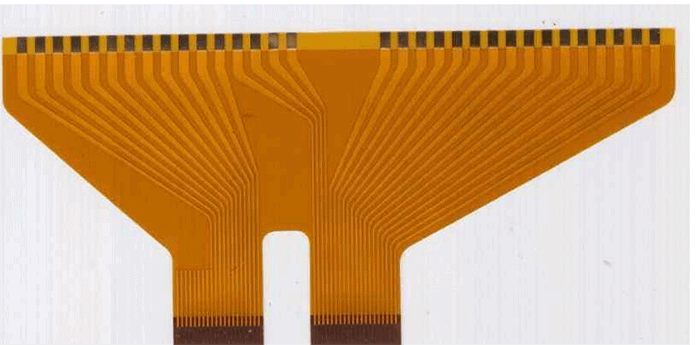
A flexible printed circuit (FPC), also known as a flex circuit, is a type of printed circuit board (PCB) made of a thin flexible dielectric material such as polyimide film. The circuits are printed or bonded onto the flexible substrate using conductive inks or copper foil. Flex circuits can be bent, folded and twisted, allowing them to conform to three-dimensional product enclosures. They are ideal for applications where space is limited, weight is critical, or flexible form factors are required.
Compared to rigid PCBs, flex circuits provide several advantages:
- Flexible and customizable form factors
- Dynamic flexing capability
- Light weight and thin profiles
- Enhanced reliability in dynamic environments
- Space and weight savings
Flex circuits are commonly found in consumer electronics, aerospace and defense products, medical devices, industrial equipment and automotive applications. As DIY makers, designers and hobbyists, we can leverage flex circuit technology in our own projects to create compact and innovative products. With some key design considerations and simple manufacturing techniques, flex circuits can be fabricated right at home.
Design Considerations for DIY Flex Circuits
When creating your own flex circuit designs, here are some important factors to keep in mind:
Flexible Substrate Material
The flexible substrate or base material is the foundation of the flex circuit. Common options include:
- Polyimide (Kapton) films: High temperature resistance, excellent chemical resistance and dielectric properties. Different thickness options.
- PET films: Lower cost but cannot withstand high temps. Various thickness options.
- PEN films: High heat resistance and can be made thinner than polyimide.
Consider the application specs when selecting the flexible substrate, including temperature range, chemical exposure, thickness and dielectric requirements.
Conductor Materials
The conductors provide the conductive paths for signals and power. Typical flex circuit conductor options:
- Copper foil: Most common due to high conductivity and low cost. Various foil thicknesses.
- Silver ink: Printable thick film pastes can be used for conductors. Provides flexibility but higher resistance than copper.
- Carbon ink: Also printable and flexible. Much higher resistivity than copper or silver.
Layer Stackup
Flex circuits can be single sided, double sided or multilayer designs. Multilayer flex stacks allow for higher circuit density and more connectivity options. Common layer sequences:
- Single sided: Conductors only on one side of the substrate. Low cost, simple.
- Double sided: Conductors on both sides. Allows more routing flexibility.
- Multilayer: 2 or more conductor layers separated by adhesive. Enables crossover routing.
Circuit Layout
Careful layout of the flex circuit conductors is critical for performance and reliability. Considerations include:
- Trace widths based on target current and conductor thickness
- Clearance distances between traces and pads for manufacturing
- Avoiding 90 degree angles on traces in dynamic bend areas
- Placing stiffeners, covers or bond areas in rigid sections
Connection and Bonding Methods
Flex-to-board connections can be made in various ways:
- Soldered connections: Requires pad finishing for solderability
- ZIF/LIF connectors: Low insertion force connectors attach flex to board
- Anisotropic conductive film: Bonds layered connections with conductive particles
- Wire bonding: Ultrasonic or thermal compression bonds
Protective Coatings
Coverlay or solder mask provides insulation and protection for the flex circuitry. Liquid photoimageable soldermask (LPI) is commonly used. Consider coverage requirements when designing.
Manufacturing Your Own Flex Circuits
Creating simple single or double sided flex circuit prototypes at home is quite feasible with DIY fabrication techniques. Here is an overview of the key manufacturing steps:
1. Design and Layout
- Create circuit layout in PCB design software
- Finalize board shape, conductor traces, pads, etc.
- Output Gerber and drill files for photoplotting
2. Photoplotting
- Print circuit layout onto transparency film
- Some home photoplotters can handle flex substrate films
- Otherwise print to transparency then transfer toner to flex material
3. Substrate Preparation
- Cut flex substrate to size using shears or precision knife
- Clean thoroughly with isopropyl alcohol
- Optional: Apply liquid soldermask and cure with UV exposure
4. Toner Transfer
- Position printed transparency over flex substrate
- Use hot laminator or clothes iron to transfer toner to flex board
- Allow to cool, remove transparency film
5. Etching
- Mix ferric chloride etchant solution
- Immerse flex board and agitate to etch away unwanted copper
- Rinse thoroughly with water to stop etching action
6. Drilling
- Import drill file into CNC machine or drill press
- Use small diameter drill bits suitable for flex boards
- Make through holes for vias and mounting holes
7. Soldering
- Apply solder paste over pads
- Position components and reflow solder
- Or hand solder components using fine tip iron
With these essential steps, it’s possible to DIY simple single sided or double sided flex circuit boards at home. While process refinements would be needed for multilayer flex stacks, this provides a great introduction to flex PCB fabrication.
Example Flex Circuit Applications
To help illustrate the design and manufacturing process, here are some example DIY flex circuit applications you can prototype at home:
Wearable Circuit
A simple wrist-worn flex circuit with LEDs and a small microcontroller. Useful for creating wearable lights or notifications.
Design Notes:
- Single sided Kapton polyimide substrate, such as 50um (2 mil) thickness
- SMD LEDs and controller IC directly soldered to circuit
- Include thin battens as stiffeners at component areas
- Kapton stiffeners at endpoints to allow fastening bands
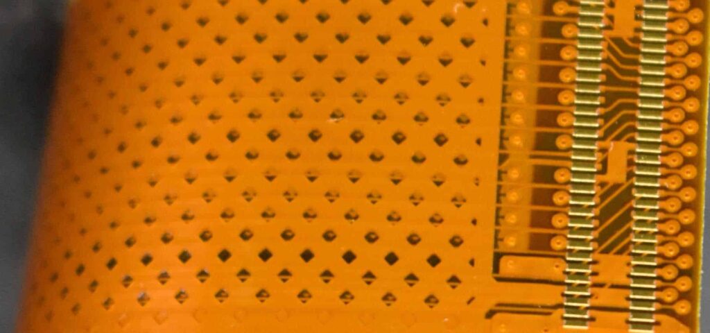
Flex Sensor Array
An array of printed flex sensors on a thin substrate that can bend and deform. Useful for flexible touch sensors or robotic skin.
Design Notes:
- Thin PET substrate, such as 25um (1 mil)
- Screen printed carbon ink traces function as flex sensors
- Arrange sensors in array patterns appropriate for application
- Ensure trace routing can handle dynamic bending
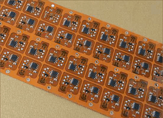
Foldable Circuit Board
A rigid-flex board that incorporates flexing hinge sections. Enables a rigid PCB to be folded into more compact 3D configurations.
Design Notes:
- Polyimide hinge sections connect rigid FR4 PCB areas
- Stiffener strips on edges of flex bends
- Vias or pads spaced apart at hinge sections
- Careful conductor routing through hinged area
Conclusion
Designing and fabricating your own flex circuit boards is an achievable DIY electronics project with the right techniques. Leveraging the advantages of flex PCBs enables innovative prototypes and products, allowing your circuits to bend, twist and deform. Start with simple single or double sided flex designs, refine your process skills, then advance to more complex rigid-flex boards as you gain experience. The world of flex awaits!
Frequently Asked Questions
Here are some common questions about DIY flex circuits:
What type of substrate material is best for DIY flex circuits?
For home fabrication, polyimide films like Kapton are a good choice. They can withstand higher temperatures which helps for toner transfer and soldering. Kapton is also chemically resistant. PET films are lower cost but cannot handle high heat or chemicals.
What thickness of copper foil should I use?
1/2 oz (18um) or 1 oz (35um) copper foils are common for DIY flex circuits. 1/2 oz provides a good balance of thickness for etching versus flexibility. 1 oz copper can be used for higher current traces.
Is special equipment needed to manufacture flex circuits at home?
You can fabricate simple flex boards using DIY equipment like laminators, clothes irons, etchant solutions, drill presses and soldering irons. For multilayer flex, specialized presses are needed.
What pitch (space) should I use between conductors?
A good starting pitch is 10 mil spacing between traces and pads. This provides clearance for etching and drilling on DIY home processes. Decrease pitch for higher density on commercial fabrication.
How small of drill bits can be used for DIY flex circuit vias?
12mil (0.3mm) diameter drill bits are readily available and can drill through flex material up to 2 mils thick. Smaller micro drills can be used with care for thinner flex boards.


Leave a Reply