Introduction
A custom flex circuit, also known as a flexible printed circuit board (FPCB), is a technology that allows circuits to be created on flexible substrates like polyimide or polyester films rather than traditional rigid boards. Flex circuits provide many advantages over rigid PCBs including flexibility, space and weight savings, improved reliability, and simplified assembly processes. This article will provide a comprehensive overview of custom flex circuit technology, design considerations, benefits, and applications.
What are Custom Flex Circuits?
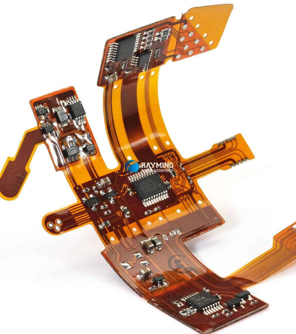
A custom flex circuit consists of conductive traces and pads photolithographically printed or etched onto a thin, flexible insulating substrate. The traces connect various components together to form an electronic circuit while maintaining the ability to bend and flex. Polyimide films like Kapton® are commonly used as base materials for their high heat resistance, chemical stability, and dielectric strength.
Flexible circuits can have portions of their length tailored to be purely flexible while other areas maintain rigidity for component mounting or connection. This enables complex geometries, three-dimensional routing, and dynamic flexing motion which would be impossible on traditional rigid boards.
Flex Circuit Design Considerations
Designing a custom flex circuit requires special considerations regarding:
Layer Stackup
The layer stackup refers to the sequence of laminated films that make up the flex circuit. A simple two-layer flex circuit has an adhesive polyimide base layer, a conductive copper trace layer, and often a coverlay protective layer. More complex designs may have multiple trace layers and bondplys or stiffeners built in for rigidity.
Trace Routing
Traces on flex circuits can make 90° turns but benefit from larger bend radii compared to rigid boards. Dynamic flexing areas require especially wide turns and gradual angles. Traces are also often hatched or meandered for increased flexibility.
Component Mounting
Components can be directly soldered or bonded to a flex circuit but usually require stiffener plates or islands for stability and flatness. Components can also be connected through cutouts or windows in the flex circuit.
Termination and Integration
Careful consideration must be made to terminate and integrate the flex circuit into other rigid components through connectors, crimping, soldering, or adhesive mounting. Strain reliefs are often needed.
Testing
Thorough testing of flex circuit prototypes throughout the full range of bending motions is critical to ensure robustness. Common tests include flexure endurance, dynamic bend lifetime, torsional twist, adhesive peel strength, and environmental stress screening.
Benefits of Flex Circuits
Custom designed flex circuits provide many advantages over traditional PCBs:
- Flexibility – Can bend, twist, fold to fit unique form factors and motions
- Thin and Lightweight – Extremely thin polyimide substrates vs rigid fiberglass boards
- Space and Weight Savings – Ideal for compact, portable electronics
- Reliability – Dynamic flexing withstands fatigue better than rigid solder joints
- Simplified Assembly – Integrated flex-rigid parts reduce connectors and assembly steps
- Heat Dissipation – Polyimide withstands high temps for electronics cooling
- High Frequency – Matched impedance controlled length lines for signals up to GHz
- Cost Savings – Reduced parts, connectors, labor compared to rigid boards
Flex Circuits vs Rigid PCBs Comparison Table
| Parameter | Flex Circuits | Rigid PCBs |
|---|---|---|
| Thickness | 0.05 – 0.4 mm | 1.6 mm |
| Layers | 1-6 | Up to 16+ |
| Minimum Trace Width | 0.1 mm | 0.2 mm |
| Minimum Bend Radius | Flexible | Fixed |
| Weight | Light | Heavy |
| Repairs | Difficult | Simple |
| Cost | $ | $$ |
Flex Circuit Materials
Polyimide films like Kapton or UPILEX are the most common flexible circuit substrates but other materials like polyester (PET) or PEEK may be used. Base material properties like flexural modulus, CTE, moisture absorption, flammability rating, UL rating, Tg and dielectric strength are important. Common flex circuit materials include:
- Polyimide – Kapton, Apical, UPILEX, Upilex-S. High temp, chemical resistance
- Polyester – PET, BoPet. Low cost, clear.
- PEN – Teonex, Tevista. Heat resistance better than PET.
- PEEK – High temp and chemical resistance
- Parylene – Used as a moisture barrier and protective coating
- Adhesives – Acrylic, epoxy, phenolic butyrals. Bond flex layers.
Cover layers may use acrylic, urethane, or epoxy adhesives. Solder masks are typically LPI or aqueous. Stiffeners embedded for rigid sections use materials like polyimide, FR4, aluminum, or stainless steel.
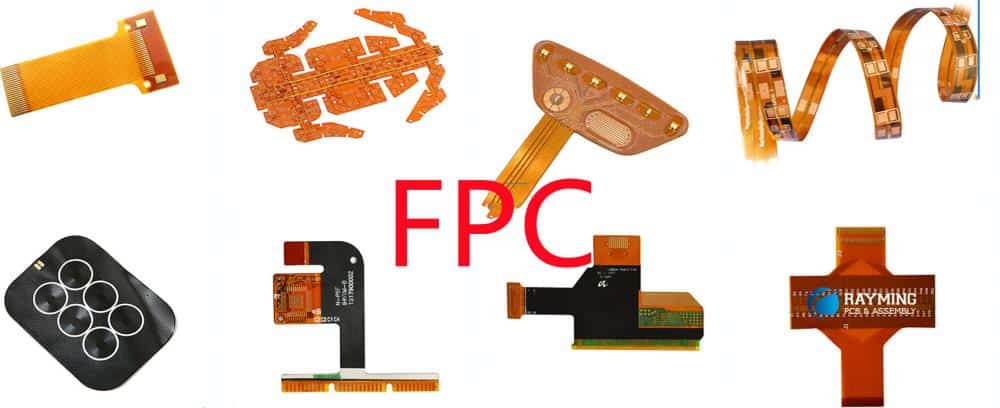
Flex Circuit Applications
The applications leveraging custom flex circuit technology span a diverse range of industries.
Consumer Electronics
Wearables, cameras, displays, sensors, antennas, and interconnects in consumer electronics all benefit from flex circuits’ small size and dynamic capabilities. Curving flex circuits around batteries or enclosures optimize the layout.
Medical
Implantable medical devices use flex circuits for their biocompatible flexibility to bend smoothly within the body. The lightweight curves also reduce loading on tiny lead wires to sensors or electrodes.
Automotive
Around vehicles, flex circuits handle vibration and tight spaces for power distribution, lighting, sensors, and body circuits. Flex-rigid boards also withstand engine bay heat while consolidating rigid PCBs.
Industrial
Industrial controls employ flex circuits for moving actuators or robot arms. The dynamic flexing withstands millions of cycles in hot, dirty, or wet environments. The flexibility also enables safer designs.
Aerospace and Defense
In air and space applications, flex circuits provide reliable interconnections that survive vibration and thermal cycles. Size and weight savings are also critical for maximizing payload.
Step-by-Step Flex Circuit Design Guide
Designing a custom flex circuit requires attention to specialized considerations but can be broken into a standard design cycle:
- Define Requirements – Specify mechanical, electrical, environmental needs along with board geometry, layers, density, line widths.
- Material Selection – Choose suitable flexible substrate, adhesives, cover layers, and stiffeners to meet requirements.
- Layout and Routing – Use flex-capable CAD tools for trace layout, minimizing rigid sections.
- Thermal Analysis – Simulate board level heating and cooling to ensure thermal dissipation.
- Mechanical Analysis – Model dynamic flexing with FEA tools to optimize trace widths and spacing.
- DFM Checks – Review design manufacturability like trace widths, spacing, laminations.
- Prototyping – Build and test initial prototypes over required temperature, humidity, and flexure cycles.
- Fabrication – Manufacture of production flex boards requires specialized processing of polyimide materials.
- Quality Testing – Perform complete environmental stress screening and inspection per IPC standards.
- Application Integration – Carefully design and test system installation for robust termination and mounting.
Working with a Flex Circuit Supplier or Manufacturer
Most companies do not have the specialized in-house expertise and manufacturing capabilities to produce flex circuits. Working with an experienced flex circuit supplier and manufacturer is highly recommended over general PCB shops. Key capabilities to seek out include:
- Design Experience – Extensive flex and rigid-flex design experience critical for complex layouts.
- Flex Materials and Adhesives – Polyimide processing know-how and sourcing of special materials.
- Reliability Testing – Environmental stress screening essential to ensure robustness.
- Quality Certifications – Operate per IPC standards and achieve certifications like AS9100.
- Flexible Volumes – Prototype through higher volume production often required.
- Design Support – Upfront DFM feedback and engineering collaboration.
Finding a supplier that meets your specific flex circuit requirements but also adds value through design support and quality processes results in the most robust product with optimized manufacturability.
Frequently Asked Questions
What are some examples of flexible circuit applications?
Flex circuits are used extensively in consumer electronics, medical devices, automotive, aerospace, and industrial applications. Common examples include wearable devices, electronic sensors, antennas, robotic arms, and implantable medical devices.
How small can flex circuit traces and spaces be?
Typical flex circuit trace/space is 75/75 microns (3/3 mils) but some designs take this down to 25/25 microns (1/1 mil) or less with tightly controlled manufacturing processes.
Can components be mounted directly on flex circuits?
Yes, components can be surface mounted but usually require stiffener plates or islands to prevent stress on solder joints. Components may also connect through cutouts or windows.
How many layers can a flex circuit have?
While 2-4 layers is typical, flex circuits can potentially have up to 6 or more layers depending on limitations of reliably laminating the thin flexible substrates.
How are components terminated on flex circuits?
SMT components can be soldered while larger connections may use mechanical clamping, soldered wires, or crimped terminals secured with adhesive. Strain relief is critical.
Conclusion
Flexible printed circuits provide the unique ability to bend and twist within electronic devices, enabling applications and designs not possible with rigid boards. Successfully designing and manufacturing a custom flex circuit requires careful consideration of the materials, tracing routing, layer stackup, termination methods, and quality processes required to produce a robust product. Finding an experienced flex circuit supplier is key to optimizing designs for manufacturability and reliability.


Leave a Reply