What is a Current Follower Circuit?
A current follower circuit, also known as a current buffer or current mirror, is an electronic circuit that produces an output current that follows or mirrors the input current. The purpose of a current follower is to provide a high impedance input and a low impedance output, allowing the circuit to act as a buffer between a current source and a load.
The basic principle of a current follower is that the output current is controlled by the input current, rather than the input voltage. This is achieved by using active devices such as transistors or operational amplifiers (op-amps) to sense the input current and adjust the output current accordingly.
Key Characteristics of Current Follower Circuits
-
High input impedance: The input stage of a current follower presents a high impedance to the current source, minimizing loading effects and ensuring accurate current sensing.
-
Low output impedance: The output stage of a current follower provides a low impedance path for the load, allowing the output current to remain constant despite variations in the load impedance.
-
Current gain: The ratio of the output current to the input current is known as the current gain. In an ideal current follower, the current gain is unity (1), meaning the output current is identical to the input current.
-
Voltage compliance: A current follower has a certain range of output voltages over which it can maintain the desired output current. This range is called the voltage compliance range and is determined by the supply voltages and the characteristics of the active devices used in the circuit.
Types of Current Follower Circuits
There are several types of current follower circuits, each with its own characteristics and applications. Some common types include:
1. Simple Current Mirror
A simple current mirror consists of two matched transistors, usually BJTs or MOSFETs, with their bases or gates connected together. The input current flows through one transistor (the reference), while the other transistor (the mirror) produces an output current that is proportional to the input current.
| Parameter | Reference Transistor | Mirror Transistor |
|---|---|---|
| Collector Current | IREF | IOUT |
| Base-Emitter Voltage | VBE,REF | VBE,MIRROR |
| Emitter Area | AREF | AMIRROR |
The output current of a simple current mirror is given by:
IOUT = (AMIRROR / AREF) × IREF
where AMIRROR and AREF are the emitter areas of the mirror and reference transistors, respectively.
2. Wilson Current Mirror
The Wilson current mirror is an improved version of the simple current mirror that provides better accuracy and output impedance. It uses three transistors and a resistor to create a feedback loop that reduces the effect of base current errors and increases the output impedance.
3. Cascode Current Mirror
A cascode current mirror combines two simple current mirrors in a cascode configuration to further increase the output impedance and improve the accuracy of the current mirroring. The cascode configuration also helps to increase the voltage compliance range of the current follower.
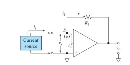
4. Operational Amplifier-Based Current Follower
An op-amp-based current follower uses an operational amplifier to sense the input current and control the output current. The op-amp’s high input impedance and low output impedance make it an ideal choice for current following applications. The basic configuration consists of an op-amp with a feedback resistor connected between its output and inverting input, while the input current is fed into the non-inverting input.

Applications of Current Follower Circuits
Current follower circuits find applications in various areas of analog and mixed-signal electronics, such as:
-
Biasing circuits: Current followers are used to provide stable and accurate bias currents to other circuits, such as amplifiers, comparators, and voltage regulators.
-
Active loads: In integrated circuits, current followers can be used as active loads to replace resistors, saving chip area and providing better performance.
-
Current-mode signal processing: Current followers are essential building blocks in current-mode circuits, where signals are represented and processed as currents rather than voltages.
-
Current sensing and measurement: Current followers can be used to sense and measure currents in power electronics, battery management systems, and other applications where accurate current monitoring is required.
-
Analog computing: Current followers are used in analog computing circuits to perform mathematical operations such as addition, subtraction, multiplication, and division on current-mode signals.

Designing Current Follower Circuits
When designing a current follower circuit, several factors must be considered to ensure optimal performance:
-
Transistor matching: In simple and Wilson current mirrors, the accuracy of the current mirroring depends on the matching between the reference and mirror transistors. Techniques such as using larger transistor sizes, interdigitated layouts, and common-centroid placement can help improve matching.
-
Bias conditions: The bias currents and voltages of the active devices in the current follower must be carefully chosen to ensure proper operation and maximize the voltage compliance range.
-
Frequency response: The bandwidth and slew rate of the current follower should be considered when designing for high-frequency applications. Techniques such as using cascode configurations and low-capacitance layouts can help improve the frequency response.
-
Temperature stability: The performance of current followers can be affected by temperature variations. Techniques such as using temperature-compensated biasing and matched transistor pairs can help improve temperature stability.
-
Noise: In low-noise applications, the noise contribution of the current follower must be minimized. Techniques such as using larger transistor sizes, optimizing bias currents, and using low-noise op-amps can help reduce noise.

FAQ
-
What is the difference between a current follower and a voltage follower?
A current follower is designed to produce an output current that follows the input current, while a voltage follower (also known as a voltage buffer) produces an output voltage that follows the input voltage. Current followers have high input impedance and low output impedance, while voltage followers have high input impedance and low output impedance. -
Can a current follower be used as a voltage amplifier?
No, a current follower cannot be used as a voltage amplifier because it is designed to produce an output current that follows the input current, not to amplify voltage signals. However, a current follower can be used in conjunction with other circuits, such as transimpedance amplifiers, to convert current signals to voltage signals with amplification. -
What is the purpose of using a cascode configuration in a current mirror?
A cascode configuration in a current mirror helps to increase the output impedance and improve the accuracy of the current mirroring. By using two transistors in series, the cascode configuration reduces the effect of the Early voltage and channel length modulation, which can cause deviations from the ideal current mirroring ratio. The cascode configuration also helps to increase the voltage compliance range of the current follower. -
How does transistor mismatch affect the performance of a current mirror?
Transistor mismatch can cause deviations from the ideal current mirroring ratio in a current mirror. If the reference and mirror transistors have different characteristics, such as threshold voltage or current gain, the output current will not be an exact copy of the input current. This can lead to inaccuracies in the current mirroring and affect the performance of the overall circuit. Techniques such as using larger transistor sizes, interdigitated layouts, and common-centroid placement can help minimize the effects of transistor mismatch. -
What are the advantages of using an op-amp-based current follower compared to a simple current mirror?
An op-amp-based current follower offers several advantages over a simple current mirror: - Higher input impedance: The op-amp’s high input impedance minimizes loading effects on the current source.
- Lower output impedance: The op-amp’s low output impedance provides a more stable output current under varying load conditions.
- Improved accuracy: The op-amp’s feedback loop helps to reduce errors caused by transistor mismatches and other non-idealities.
- Greater flexibility: The op-amp-based design allows for easy modification of the current gain by changing the feedback resistor value.
However, op-amp-based current followers may have higher power consumption and limited bandwidth compared to simple current mirrors.
In conclusion, current follower circuits are essential building blocks in analog and mixed-signal electronics, providing a means to buffer, mirror, and process current-mode signals. By understanding the basic principles, types, and design considerations of current followers, engineers can effectively utilize these circuits in a wide range of applications, from biasing and active loads to current-mode signal processing and analog computing.


Leave a Reply