Introduction
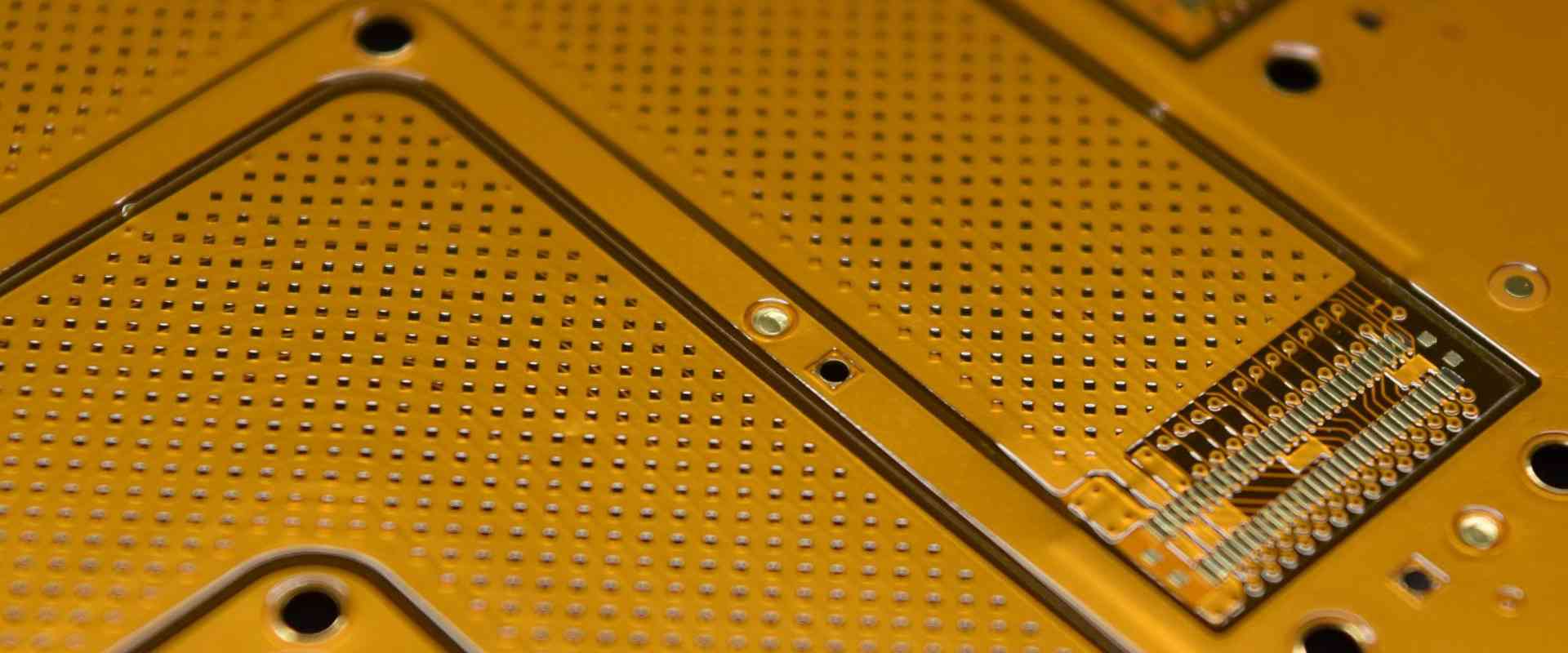
Flexible printed circuit boards (PCBs), also known as flex circuits, are made with flexible dielectric substrates. Coverlay is a protective layer laminated over the surface of a flex PCB to prevent oxidation and provide mechanical support. Coverlay flex PCBs have become ubiquitous in modern electronic devices due to their many advantages. In this article, we will explore coverlay technology in depth – its design, materials, production methods and applications across industries.
What is Coverlay?
Coverlay is a thin, flexible dielectric film that is laminated onto flex circuits to protect the traces on the board. Polyimide films like Kapton are most commonly used as coverlay, although other polymers like PEEK and PET are also options. The main purposes of coverlay are:
- Protecting circuits: The coverlay shields the copper traces on the flex PCB from physical damage and prevents oxidation.
- Insulating circuits: It provides electrical isolation between overlapping circuit traces.
- Providing solder dams: Coverlay acts as a solder mask to prevent solder from bridging between contact fingers during assembly.
- Imparting mechanical support: It reinforces the flex circuit and makes it more rugged.
Coverlay films typically have a thickness between 12.5-100 microns. Adhesives such as acrylic or epoxy are used to bond the coverlay to the base dielectric of the flex PCB.
Benefits of Using Coverlay
Here are some of the major benefits of coverlay flex PCBs:
- Durability: Coverlay protects circuits from abrasions, scratches and handling damage. This allows flex PCBs to be used in dynamic applications.
- Reliability: Coverlay prevents copper traces from oxidizing over time, enhancing the reliability and lifetime of circuits.
- Insulation: It provides electrical isolation for overlapping or closely-spaced conductors on high density flex circuits.
- Aesthetics: Coverlay provides a clean, professional finish to flex PCBs. Brand logos and markings can be added to the coverlay.
- Simplified assembly: Coverlay acts as a solder mask for easier component mounting and soldering.
- Weight savings: Using coverlay allows thinner base dielectrics to be used, reducing weight.
Coverlay Flex PCB Design Considerations
Designers should keep the following guidelines in mind when designing coverlay flex PCBs:
- Coverlay openings must provide adequate spacing from conductors to prevent shorts. A minimum clearance of 0.05-0.1mm is recommended.
- Avoid putting coverlay over vias and testpoints which must be accessible.
- Minimize the number of layers to reduce thickness and maximize flexibility. 1-2 layer designs are optimal.
- Use gradual bends in traces to prevent conductor cracking. Avoid 90° angles.
- Strategically place coverlay to maximize protection on the most vulnerable areas.
- Allow 0.1-0.2mm annular ring around pad openings in coverlay for solder mask registration.
- Specify coverlay type, thickness and bond ply if the flex PCB will undergo harsh environmental testing.
Coverlay Flex PCB Materials
Polyimide films dominate as the coverlay material of choice for their electrical performance, flexibility, temperature resistance and durability. Here are some common options:
- Kapton: Dupont’s Kapton polyimide film is the most popular and widely used coverlay material. It has excellent mechanical properties and temperature resistance up to 400°C.
- Upilex: Ube’s Upilex offers similar performance to Kapton but has lower moisture absorption. It is well-suited for applications involving high humidity.
- Kaptrex: DuPont’s Kaptrex coverlay is a composite of Kapton bonded with Teflon fibers, improving its dimensional stability and flex life.
- Pyralux: Dupont’s Pyralux polyimide coverlay has high temperature resistance and conformability. It bonds well to acrylic adhesives.
- Ultem: GE’s Ultem polyetherimide (PEI) coverlay withstands higher temperatures than Kapton, up to 170°C continuous use.
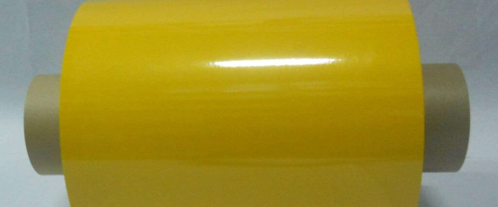
Coverlay is typically supplied in roll form with an acrylic or epoxy adhesive on one side. Common adhesive thicknesses are 25μm or 50μm. The adhesive must be chemically compatible with the base dielectric on the flex PCB.
Coverlay Application and Bonding
Coverlay application involves carefully laminating the coverlay film onto the fabricated flex PCB. Here is an overview of the standard process:
- The coverlay roll is cut to the appropriate dimensions and punched or laser cut to the required openings.
- Precise alignment is performed to register the coverlay openings to the substrate features.
- The release liner is peeled off the adhesive side of the coverlay film.
- The coverlay is laminated onto the flex circuit using a specialized vacuum laminator.
- The assembly passes through a lamination oven where heat and pressure activate the adhesive.
- The laminate travels through a chilling station to quickly solidify the adhesive bond.
- Any post-lamination cleaning or annealing processes are conducted.
The quality of the adhesive bond between coverlay and substrate impacts the lifespan of the flex PCB. Flex boards may undergo environmental stress testing to verify the coverlay’s performance.
| Coverlay Bonding Methods | Key Characteristics |
|---|---|
| Thermal Compression | Uses heat and pressure <br> Strongest bond <br> Suitable for thick coverlay |
| Adhesive Curing | Room temperature curing adhesives <br> Lower cost <br> Thinner coverlay compatible |
| Ultrasonic Welding | Uses high-frequency vibrations <br> Fast process <br> Minimal heating |
Rigid-Flex PCBs with Coverlay
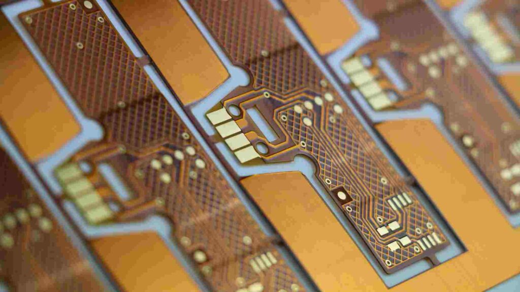
Rigid-flex PCBs contain both rigid and flexible substrates interconnected on one board. Coverlay is an important requirement for the flexible sections of rigid-flex boards to provide protection and prevent copper wicking. Without coverlay, repeated flexing can cause cracks in the conductor traces.
For rigid-flex designs, coverlay lamination is performed after board fabrication since the rigid and flex sections move at different rates during lamination which can cause registration issues. Laser-cut coverlay is often preferred over punched coverlay for rigid-flex applications due to better dimensional control.
Environmental Performance Testing
Coverlay flex PCBs intended for use under challenging operating environments undergo standardized qualification testing to verify the coverlay materials meet specifications. Some common tests performed are:
- Flexural endurance: Evaluates coverlay performance under dynamic bending stresses.
- Adhesion: Tests the bond strength between coverlay and substrate dielectric.
- Solder shock: Simulates soldering thermal shocks to validate coverlay reliability.
- Temperature cycling: Alternately exposes board to extreme high and low temps.
- Moisture resistance: Validates performance in high humidity environments.
- Chemical resistance: Checks compatibility when exposed to different chemical agents.
Only coverlay that passes all required test protocols can be used in demanding applications like automotive, aerospace and medical electronics.
Applications of Coverlay Flex Circuits
The versatile properties of coverlay flex PCBs make them suitable for the following types of applications:
Consumer Electronics
Coverlay polyimide films allow flex PCBs to withstand the twisting and bending required in consumer devices like:
- Mobile phones
- Laptops and tablets
- Digital cameras
- Wearable devices
- Game controllers
Automotive Electronics
Coverlay’s resistance to vibration, shocks and temperature fluctuations suits it for use in automotive applications like:
- Drive control systems
- Monitoring cameras
- Battery management systems
- Lighting controls
- In-vehicle entertainment
Medical Devices
Coverlay provides extra protection for flexible circuits used in medical devices that undergo sterilization and cleaning:
- Hearing aids
- Patient monitoring systems
- Surgical equipment
- Diagnostic imaging
- Prosthetics
Industrial
Rugged coverlay allows reliable performance of flex PCBs used in harsh industrial settings:
- Process control equipment
- Machine vision systems
- Robotics
- Oil and gas instrumentation
Aerospace and Defense
Coverlay’s durability makes it well-suited for mission-critical aerospace systems:
- Avionics
- Missile guidance
- Radar and communication
- Satellites
- Space vehicles
In summary, coverlay flex PCBs empower the next-generation of compact, lightweight and reliable electronic devices across every industry. With coverlay technology continuing to advance, flex circuits will find expanding roles enabling new applications and form factors.
Frequently Asked Questions
What are some pros and cons of coverlay flex PCBs?
Pros:
- Protection for circuits from damage
- Insulation between conductors
- Solder masks for easier assembly
- Reinforcement of flex board
- Allows thinner, lighter constructions
Cons:
- Additional production step
- Potential for registration errors
- Increased cost over bare flex
- Stiffness impacts flexing performance
How is coverlay aligned to the flex PCB during lamination?
Precise optical registration systems are used to align coverlay openings to the substrate features prior to lamination. Holes or fiducials in the coverlay film provide reference points for alignment. Vision systems identify the exact position of substrate pads and traces beneath the coverlay.
Are there alternative protective coatings besides coverlay?
Conformal coatings like parylene or silicone can be selectively applied to protect traces. However, they lack coverlay’s insulation capabilities. Liquid photoimageable (LPI) solder masks are another alternative but have limited flexibility compared to coverlay films.
How are openings formed in coverlay?
Punching with steel tools is an economical process for making coverlay openings. Punching produces some edge burrs so clearance from conductors is necessary. Laser cutting offers cleaner, more precise openings and is used for fine pitch designs.
What are some key factors in selecting coverlay?
Key considerations include dielectric type, temperature rating, flexibility, bond ply adhesive type, thickness, dielectric constant, loss tangent, dimensional stability, moisture absorption, chemical resistance, flammability rating and cost.


Leave a Reply