Introduction to Colpitts Oscillator
The Colpitts oscillator is a type of electronic oscillator circuit that generates a sinusoidal output waveform using a combination of inductors and capacitors. It is named after its inventor, Edwin H. Colpitts, who patented the design in 1918. The Colpitts oscillator is widely used in various electronic applications, including radio frequency (RF) circuits, signal generators, and telecommunication systems.
Basic Principle of Operation
The basic principle behind the Colpitts oscillator is the use of an LC tank circuit, which consists of an inductor (L) and two capacitors (C1 and C2) connected in series. The capacitors form a voltage divider network that provides positive feedback to the active device, typically a transistor or an operational amplifier.
The oscillation frequency of a Colpitts oscillator is determined by the values of the inductor and capacitors in the tank circuit, and can be calculated using the following formula:
f = 1 / (2π√(LC))
where:
– f is the oscillation frequency in Hertz (Hz)
– L is the inductance in Henries (H)
– C is the equivalent capacitance of C1 and C2 in Farads (F), given by:
C = (C1 * C2) / (C1 + C2)
Advantages of Colpitts Oscillator
The Colpitts oscillator offers several advantages over other types of oscillator circuits:
-
Simplicity: The Colpitts oscillator requires fewer components compared to other oscillator designs, making it simpler to construct and more cost-effective.
-
Frequency stability: The Colpitts oscillator exhibits excellent frequency stability, especially when using high-quality components and proper circuit layout techniques.
-
Wide frequency range: By varying the values of the inductor and capacitors, the Colpitts oscillator can generate a wide range of frequencies, from a few kilohertz (kHz) to several gigahertz (GHz).
-
Low harmonic distortion: The Colpitts oscillator produces a relatively pure sinusoidal output waveform with low harmonic distortion, making it suitable for applications that require a clean signal.
Colpitts Oscillator Circuit Design
Basic Circuit Configuration
The basic circuit configuration of a Colpitts oscillator consists of the following components:
- An inductor (L)
- Two capacitors (C1 and C2)
- An active device (transistor or operational amplifier)
- Biasing Resistors and capacitors
The inductor and capacitors form the LC tank circuit, which determines the oscillation frequency. The active device provides the necessary gain and feedback to sustain the oscillations.
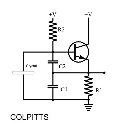
Transistor-based Colpitts Oscillator
In a transistor-based Colpitts oscillator, a bipolar junction transistor (BJT) or a field-effect transistor (FET) is used as the active device. The transistor is biased in the active region, and the LC tank circuit is connected between the collector (or drain) and the emitter (or source) of the transistor.
The following table summarizes the key components and their functions in a transistor-based Colpitts oscillator:
| Component | Function |
|---|---|
| Transistor | Provides gain and feedback |
| Inductor (L) | Forms the LC tank circuit with C1 and C2 |
| Capacitor (C1) | Forms the LC tank circuit and provides feedback |
| Capacitor (C2) | Forms the LC tank circuit and provides feedback |
| Biasing resistors | Set the operating point of the transistor |
| Bypass capacitors | Provide AC ground and prevent signal attenuation |
Op-Amp-based Colpitts Oscillator
An operational amplifier (op-amp) can also be used as the active device in a Colpitts oscillator. In this configuration, the LC tank circuit is connected between the output and the non-inverting input of the op-amp, while the inverting input is grounded.
The op-amp provides the necessary gain and feedback to maintain the oscillations. The oscillation frequency is determined by the values of the inductor and capacitors in the tank circuit.

Applications of Colpitts Oscillator
The Colpitts oscillator finds application in various electronic systems, including:
Radio Frequency (RF) Circuits
Colpitts oscillators are commonly used in RF circuits, such as:
- Wireless communication systems
- Radio transmitters and receivers
- Frequency synthesizers
In these applications, the Colpitts oscillator generates the carrier frequency or the local oscillator signal for frequency mixing and demodulation.
Signal Generators
Colpitts oscillators are used in signal generators to produce sinusoidal test signals with a wide range of frequencies. These signal generators are essential tools for testing and characterizing electronic circuits and systems.
Telecommunication Systems
In telecommunication systems, Colpitts oscillators are employed in various roles, such as:
- Generating clock signals for synchronization
- Modulating and demodulating signals
- Frequency conversion and synthesis
The Colpitts oscillator’s simplicity, frequency stability, and wide frequency range make it a suitable choice for these applications.

Designing and Optimizing Colpitts Oscillators
To design and optimize a Colpitts oscillator for a specific application, consider the following factors:
Frequency Stability
Frequency stability is a critical factor in oscillator design. To improve the frequency stability of a Colpitts oscillator:
- Use high-quality, temperature-stable components (e.g., NP0 or C0G capacitors, low-drift inductors)
- Minimize Stray Capacitances and inductances in the circuit layout
- Provide a stable power supply with adequate decoupling
- Use a voltage regulator to minimize supply voltage variations
Output Waveform Quality
To achieve a clean sinusoidal output waveform with low harmonic distortion:
- Ensure that the active device (transistor or op-amp) is operating in its linear region
- Use a high-Q inductor and capacitors in the tank circuit
- Minimize the loading effect on the tank circuit by using a buffer stage
- Adjust the feedback network to maintain the desired oscillation amplitude
Frequency Tuning
In some applications, it may be necessary to tune the oscillation frequency of the Colpitts oscillator. This can be achieved by:
- Using a variable capacitor (varactor diode) in parallel with one of the tank capacitors
- Employing a mechanically adjustable inductor (e.g., a slug-tuned inductor)
- Implementing a phase-locked loop (PLL) for precise frequency control

Frequently Asked Questions (FAQ)
-
What is the main difference between a Colpitts oscillator and a Hartley oscillator?
The main difference between a Colpitts oscillator and a Hartley oscillator lies in the configuration of the LC tank circuit. In a Colpitts oscillator, the tank circuit consists of an inductor and two series-connected capacitors, while in a Hartley oscillator, the tank circuit comprises two inductors and a single capacitor. -
Can a Colpitts oscillator be used for low-frequency applications?
Yes, a Colpitts oscillator can be used for low-frequency applications by selecting appropriate values for the inductor and capacitors in the tank circuit. However, for very low frequencies (below a few kilohertz), the required component values may become impractically large, and other oscillator topologies, such as the Wien bridge oscillator or the RC phase-shift oscillator, may be more suitable. -
How does the choice of the active device affect the performance of a Colpitts oscillator?
The choice of the active device (transistor or op-amp) in a Colpitts oscillator affects its performance in terms of gain, frequency range, and output waveform quality. Transistors are generally preferred for high-frequency applications, while op-amps are better suited for lower frequencies. The active device’s noise characteristics, linearity, and bandwidth also influence the oscillator’s overall performance. -
What is the role of the feedback network in a Colpitts oscillator?
The feedback network in a Colpitts oscillator, formed by the two capacitors in the tank circuit, provides the necessary positive feedback to sustain the oscillations. The ratio of the capacitor values determines the amount of feedback and the oscillation amplitude. Proper design of the feedback network is crucial for achieving stable oscillations with the desired amplitude and waveform quality. -
How can the output power of a Colpitts oscillator be increased?
To increase the output power of a Colpitts oscillator, you can: - Use a higher-power active device (transistor or op-amp) with a larger current handling capability
- Increase the supply voltage, ensuring that the active device remains within its safe operating limits
- Employ an output buffer stage with a higher current drive capability
- Optimize the impedance matching between the oscillator and the load to maximize power transfer
Conclusion
The Colpitts oscillator is a versatile and widely used electronic oscillator circuit that offers simplicity, frequency stability, and a wide frequency range. Its applications span various domains, including RF circuits, signal generators, and telecommunication systems.
By understanding the basic principles, circuit design, and optimization techniques of Colpitts oscillators, engineers and hobbyists can effectively implement them in their projects and tailor their performance to specific requirements.
As with any oscillator design, careful component selection, proper circuit layout, and attention to factors such as frequency stability, output waveform quality, and frequency tuning are essential for achieving the desired performance and reliability.
With its rich history and continued relevance in modern electronics, the Colpitts oscillator remains an indispensable tool in the designer’s arsenal, enabling the generation of stable, high-quality sinusoidal signals for a wide range of applications.


Leave a Reply