Introduction to Clap Switch
A clap switch is an electronic device that can be used to turn electrical appliances on or off by simply clapping your hands. It is a fun and easy project for beginners who are interested in learning about electronics and circuit design. In this article, we will discuss the basics of a clap switch, its components, how it works, and how to build one yourself.
What is a Clap Switch?
A clap switch is a device that uses a microphone to detect the sound of clapping and then triggers a relay to turn an electrical appliance on or off. It is a simple and convenient way to control electrical devices without having to physically touch them. Clap switches are often used in homes, offices, and other settings where hands-free control of electrical devices is desired.

Components of a Clap Switch
To build a clap switch, you will need the following components:
| Component | Quantity |
|---|---|
| Microphone | 1 |
| Op-amp IC (LM358) | 1 |
| Transistor (BC547) | 1 |
| Relay (5V) | 1 |
| Diode (1N4007) | 1 |
| Resistors (10kΩ, 100kΩ, 1MΩ) | 1 each |
| Capacitors (10µF, 100µF) | 1 each |
| PCB Board | 1 |
| Connecting wires | As required |
Microphone
The microphone is the most important component of a clap switch. It is used to detect the sound of clapping and convert it into an electrical signal. There are different types of microphones available, but for this project, we will be using an Electret Microphone.
Op-amp IC (LM358)
An op-amp (operational amplifier) is used to amplify the electrical signal from the microphone. We will be using the LM358 IC, which is a dual op-amp that can be used for various applications.
Transistor (BC547)
A transistor is used as a switch to control the relay. We will be using the BC547 transistor, which is a common NPN transistor used in electronic circuits.
Relay (5V)
A relay is an electromechanical switch that is used to control high-power devices using a low-power signal. We will be using a 5V relay in this project.
Diode (1N4007)
A diode is used to protect the transistor from the back EMF (electromotive force) generated by the relay coil when it is switched off.
Resistors (10kΩ, 100kΩ, 1MΩ)
Resistors are used to limit the current flow in the circuit and to set the gain of the op-amp.
Capacitors (10µF, 100µF)
Capacitors are used to filter out noise and to smooth the power supply.
PCB board
A PCB (printed circuit board) is used to mount the components and to make the connections between them.
Connecting wires
Connecting wires are used to make the connections between the components on the PCB board.

How Does a Clap Switch Work?
A clap switch works by detecting the sound of clapping and then triggering a relay to turn an electrical appliance on or off. The basic working principle of a clap switch is as follows:
- The microphone detects the sound of clapping and converts it into an electrical signal.
- The electrical signal from the microphone is amplified by the op-amp.
- The amplified signal is then fed into the transistor, which acts as a switch.
- When the amplified signal is strong enough, it turns on the transistor, which in turn activates the relay.
- The relay switches the electrical appliance on or off.

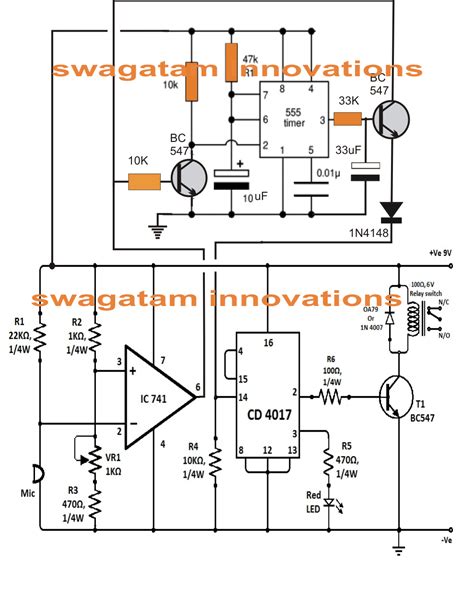
Circuit Diagram of a Clap Switch
The circuit diagram of a clap switch is shown below:
“`
+5V
|
+-+
| |
| |
|
| |
|
|
|
|
|
|
|
|
|
|
|
|
|
|
|
|
|
|
|
|
|
|
|
|
|
|
|
|
|
|
|
|
|
|
|
|
|
|
|
|
|
|
|
|
|
|
|
|
|
|
|
|
|
|
|
|
|
|
|
|
|
|
|
|
|
|
|
|
|
|
|
|
|
|
|
|
|
|
|
|
|
|
|
|
|
|
|
|
|
|
|
|
|
|
|
|
|
|
|
|
|
|
|
|
|
|
|
|
|
|
|
|
|
|
|
|
|
|
|
|
|
|
|
|
|
|
|
|
|
|
|
|
|
|
|
|
|
|
|
|
|
|
|
|
|
|
|
|
|
|
|
|
|
|
|
|
|
|
|
|
|
|
|
|
|
|
|
|
|
|
|
|
|
|
|
|
|
|
|
|
|
|
|
|
|
|
|
|
|
|
|
|
|
|
|
|
|
|
|
|
|
|
|
|
|
|
|
|
|
|
|
|
|
|
|
|
|
|
|
|
|
|
|
|
|
|
|
|
|
|
|
|
|
|
|
|
|
|
|
|
|
|
|
|
|
|
|
|
|
|
|
|
|
|
|
|
|
|
|
|
|
|
|
|
|
|
|
|
|
|
|
|
|
|
|
|
|
|
|
|
|
|
|
|
|
|
|
|
|
|
|
|
|
|
|
|
|
|
|
|
|
|
|
|
|
|
|
|
|
|
|
|
|
|
|
|
|
|
|
|
|
|
|
|
|
|
|
|
|
|
|
|
|
|
|
|
|
|
|
|
|
|
|
|
|
|
|
|
|
|
|
|
|
|
|
|
|
|
|
|
|
|
|
|
|
|
|
|
|
|
|
|
|
|
|
|
|
|
|
|
|
|
|
|
|
|
|
|
|
|
|
|
|
|
|
|
|
|
|
|
|
|
|
|
|
|
|
|
|
|
|
|
|
|
|
|
|
|
|
|
|
|
|
|
|
|
|
|
|
|
|
|
|
|
|
|
|
|
|
|
|
|
|
|
|
|
|
|
|
|
|
|
|
|
|
|
|
|
|
|
|
|
|
|
|
|
|
|
|
|
|
|
|
|
|
|
|
|
|
|
|
|
|
|
|
|
|
|
|
|
|
|
|
|
|
|
|
|
|
|
|
|
|
|
|
|
|
|
|
|
|
|
|
|
|
|
|
|
|
|
|
|
|
|
|
|
|
|
|
|
|
|
|
|
|
|
|
|
|
|
|
|
|
|
|
|
|
|
|
|
|
|
|
|
|
|
|
|
|
|
|
|
|
|
|
|
|
|
|
|
|
|
|
|
|
|
|
|
|
|
|
|
|
|
|
|
|
|
|
|
|
|
|
|
|
|
|
|
|
|
|
|
|
|
|
|
|
|
|
|
|
|
|
|
|
|
|
|
|
|
|
|


Leave a Reply