ALL ABOUT FLEX PCB
-
Flip chip Resistor Performance Improved
Posted by
–
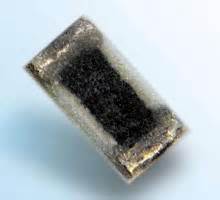
Read more: Flip chip Resistor Performance ImprovedIntroduction to Flip-chip resistors Flip-chip resistors are a type of surface-mount resistor that offers improved performance compared to traditional resistor packages. They utilize a unique manufacturing process where the resistive element is flipped upside down and connected to the substrate using conductive bumps. This innovative design enables better thermal management, lower parasitic inductance, and enhanced…
-
Pcb for wired printing head fabtotum
Posted by
–
 Read more: Pcb for wired printing head fabtotum
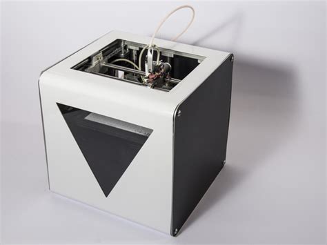
Introduction to Fabtotum PCB Fabtotum is an innovative all-in-one 3D printer, scanner, and CNC machine that has revolutionized the world of personal fabrication. One of the key components of this versatile machine is its printed circuit board (PCB) for the wired printing head. This PCB plays a crucial role in enabling the Fabtotum to perform…
-
Axial Flux Permanent magnet BLDC Stator
Posted by
–
 Read more: Axial Flux Permanent magnet BLDC Stator
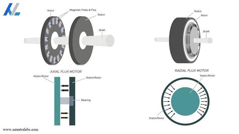
Introduction to Axial Flux BLDC Motors Axial flux permanent magnet brushless DC (BLDC) motors have gained significant attention in recent years due to their high power density, efficiency, and compact design. Unlike traditional radial flux motors, axial flux motors have their magnetic flux flowing parallel to the rotational axis, resulting in a disc-shaped structure. This…
-
Soldermask requirements for high CTI boards
Posted by
–
 Read more: Soldermask requirements for high CTI boards
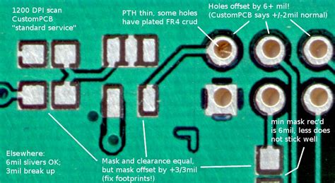
What is Soldermask CTI? Soldermask Comparative Tracking Index (CTI) is a measure of the electrical insulation properties and resistance to tracking (formation of conductive paths) of the soldermask material used on printed circuit boards (PCBs). It indicates the voltage at which the soldermask will fail and allow current to “track” between conductors, potentially causing a…
-
How does double sided SMT assembly work
Posted by
–
 Read more: How does double sided SMT assembly work
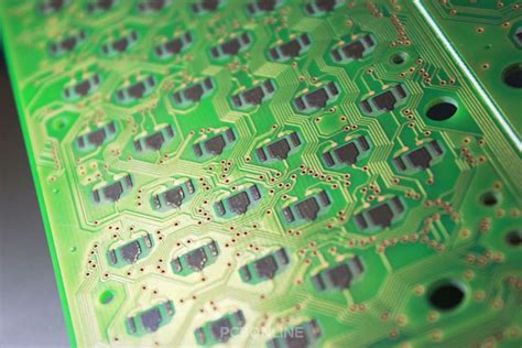
Introduction to Double-sided SMT Assembly Double-sided Surface Mount Technology (SMT) assembly is a sophisticated manufacturing process that allows electronic components to be mounted on both sides of a Printed Circuit Board (PCB). This advanced technique has revolutionized the electronics industry by enabling the production of compact, high-density, and cost-effective electronic devices. In this comprehensive article,…
-
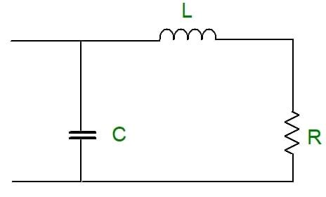 Read more: Introduction to PCB design of impedance matching with zero resistance
What is Impedance Matching? Impedance matching refers to the practice of designing the impedance of a load to match the impedance of the transmission line or source delivering power to the load. When impedances are matched, maximum power transfer occurs and signal reflections are minimized. Impedance mismatches can lead to signal degradation, reduced efficiency, and…
-
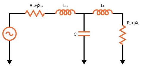 Read more: The Origin of Impedance Matching of 50 ohms in RF Design
Introduction to Challenges and Limitations Impedance Mismatches and Reflections Although the 50-ohm standard has many advantages, it is not without challenges. One of the main issues is impedance mismatches that can occur when connecting components with different impedances. Even with the 50-ohm standard, slight variations in impedance can lead to signal reflections and power loss.…
-
What is Carbon Ink PCB – A Complete Introduction
Posted by
–
 Read more: What is Carbon Ink PCB – A Complete Introduction
What is Carbon Ink PCB? Carbon ink PCB is a type of printed circuit board that utilizes conductive carbon-based ink to create electronic circuits on a substrate material, such as paper or plastic. Unlike conventional PCBs that use copper traces, carbon ink PCBs employ a special formulation of carbon-based ink that exhibits excellent electrical conductivity…
-
 Read more: What is High Frequency PCB? Its Structure and Types
Understanding High-Frequency PCBs What is a High-Frequency PCB? A high-frequency PCB is a printed circuit board that is specifically designed to handle high-frequency signals. These PCBs are engineered to minimize signal loss, distortion, and interference, which are common issues when dealing with high-frequency signals. They are manufactured using special materials and techniques to ensure optimal…
-
 Read more: High-Frequency PCB RF Microwave PCB Manufacturing at One-Stop
Introduction to High-Frequency PCBs High-frequency printed circuit boards (PCBs) are specialized boards designed to operate at high frequencies, typically above 1 GHz. These PCBs are crucial components in various applications, including RF and microwave systems, telecommunications, aerospace, and defense industries. High-frequency PCBs require specific design considerations, materials, and manufacturing processes to ensure optimal performance and…


