Introduction to Audio preamplifiers
An audio preamplifier is an essential component in any audio system, responsible for amplifying low-level signals from sources such as microphones, turntables, or CD players to a level suitable for further processing or amplification. The main purpose of a preamplifier is to boost the signal while introducing minimal noise and distortion, ensuring that the original audio signal remains as clean and accurate as possible.
Key Characteristics of Audio Preamplifiers
When designing or selecting an audio preamplifier, several key characteristics should be considered:
- Gain: The amount of amplification provided by the preamplifier, typically measured in decibels (dB).
- Noise: The unwanted background noise introduced by the preamplifier, which should be minimized to maintain signal clarity.
- Distortion: The degree to which the preamplifier alters the original signal, introducing unwanted harmonics or other artifacts.
- Frequency response: The ability of the preamplifier to accurately amplify signals across the entire audio frequency range (typically 20 Hz to 20 kHz).
- Input and output impedance: The compatibility of the preamplifier with the source and destination devices in terms of electrical impedance.
Types of Audio Preamplifiers
There are several types of audio preamplifiers, each with its own unique characteristics and applications:
1. Solid-state Preamplifiers
Solid-state preamplifiers use semiconductor devices such as transistors or integrated circuits (ICs) to amplify the audio signal. They are known for their reliability, low cost, and compact size. Some popular solid-state preamplifier designs include:
- Operational amplifier (op-amp) based preamplifiers: These utilize high-performance op-amps to provide accurate and linear amplification.
- Discrete transistor preamplifiers: These designs use individual transistors to achieve specific sound characteristics or higher performance levels.
2. Vacuum Tube Preamplifiers
Vacuum tube preamplifiers, also known as valve preamplifiers, use vacuum tubes to amplify the audio signal. They are prized by many audiophiles for their warm, rich sound and smooth distortion characteristics. Some popular vacuum tube preamplifier designs include:
- Single-ended triode (SET) preamplifiers: These use a single triode vacuum tube per channel, providing a simple and often high-quality amplification solution.
- Push-pull preamplifiers: These designs use multiple vacuum tubes in a balanced configuration to reduce distortion and increase power output.
3. Hybrid Preamplifiers
Hybrid preamplifiers combine both solid-state and vacuum tube technologies to achieve the benefits of both designs. They often use vacuum tubes in the input stage for their desirable sound characteristics and solid-state devices in the output stage for their reliability and power handling capabilities.

Designing a Low Noise Audio Preamplifier
When designing a low noise audio preamplifier, several factors must be considered to minimize noise and ensure optimal performance. Some key design considerations include:
1. Component Selection
The selection of high-quality, low-noise components is crucial for achieving a low noise preamplifier design. This includes:
- Low-noise resistors: Metal film or wire-wound resistors are often preferred for their low noise properties.
- High-quality capacitors: Polypropylene or polystyrene capacitors are known for their low dielectric absorption and excellent noise performance.
- Low-noise semiconductors: Carefully selected transistors or ICs with low noise specifications should be used in the signal path.
2. Power Supply Design
A clean and stable power supply is essential for minimizing noise in the preamplifier. Some key power supply design considerations include:
- Regulation: Using Voltage Regulators to provide a stable and ripple-free power source to the preamplifier circuitry.
- Filtering: Implementing adequate filtering, such as RC networks or LC filters, to remove high-frequency noise from the power supply rails.
- Grounding: Ensuring a proper grounding scheme to minimize ground loops and other noise-inducing issues.
3. Circuit Topology
The choice of circuit topology can greatly impact the noise performance of the preamplifier. Some popular low-noise preamplifier topologies include:
- Differential amplifiers: These designs use a balanced input stage to cancel out common-mode noise and provide high common-mode rejection.
- Cascode amplifiers: This topology uses multiple transistors in series to reduce the effect of Miller capacitance and improve high-frequency performance.
- Shunt-feedback amplifiers: These designs use a feedback network to reduce distortion and improve linearity, while also providing good noise performance.
4. Layout and Shielding
Proper circuit layout and shielding techniques are crucial for minimizing noise pickup and interference in the preamplifier. Some key considerations include:
- Component placement: Carefully placing components to minimize the length of sensitive signal paths and reduce the potential for noise pickup.
- Ground plane: Using a solid ground plane to provide a low-impedance return path for signals and minimize ground loops.
- Shielding: Enclosing sensitive circuitry in a metal shield to protect against electromagnetic interference (EMI) and radio frequency interference (RFI).

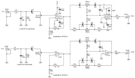
Example Low Noise Preamplifier Circuit diagram
Here is an example of a simple, low noise preamplifier circuit using a high-performance op-amp:
[Insert circuit diagram here]
Components:
– U1: NE5532 or similar low-noise op-amp
– R1, R3: 10 kΩ metal film resistors
– R2: 100 kΩ metal film resistor
– C1, C3: 10 µF electrolytic capacitors
– C2: 22 pF ceramic capacitor
This circuit uses a non-inverting amplifier configuration with a gain of 11 (20.8 dB), set by the ratio of R2 to R1. The NE5532 op-amp is known for its low noise and high slew rate, making it an excellent choice for audio preamplifier applications. The input and output capacitors (C1 and C3) provide DC blocking, while C2 acts as a high-frequency compensation capacitor to ensure stability.

Preamplifier Performance Metrics
When evaluating the performance of an audio preamplifier, several key metrics should be considered:
1. Signal-to-Noise Ratio (SNR)
The signal-to-noise ratio is a measure of the preamplifier’s ability to amplify the desired signal while minimizing background noise. It is typically expressed in decibels (dB) and calculated as:
SNR = 20 * log10(Vsignal / Vnoise)
Where Vsignal is the maximum signal level and Vnoise is the noise level with no signal present. A higher SNR indicates better noise performance.
2. Total Harmonic Distortion (THD)
Total harmonic distortion is a measure of the degree to which the preamplifier introduces unwanted harmonics into the signal. It is typically expressed as a percentage and calculated as:
THD = (Vharmonics / Vfundamental) * 100%
Where Vharmonics is the sum of the voltages of all the harmonic components and Vfundamental is the voltage of the fundamental frequency component. A lower THD indicates better linearity and less distortion.
3. Intermodulation Distortion (IMD)
Intermodulation distortion occurs when two or more signals at different frequencies interact in a non-linear system, creating new frequency components that were not present in the original signal. IMD is typically measured using a two-tone test and expressed as a percentage, similar to THD. A lower IMD indicates better linearity and less distortion.
4. Frequency Response
The frequency response of a preamplifier is a measure of its ability to accurately amplify signals across the entire audio frequency range. It is typically expressed as a deviation in decibels (dB) from a reference level, across a specified frequency range (e.g., 20 Hz to 20 kHz). A flat frequency response indicates that the preamplifier is capable of accurately amplifying signals without introducing unwanted tonal changes.
| Metric | Ideal Value | Acceptable Range |
|---|---|---|
| SNR | >100 dB | 80 dB – 100 dB |
| THD | <0.001% | 0.001% – 0.01% |
| IMD | <0.01% | 0.01% – 0.1% |
| Frequency Response | ±0 dB (20 Hz – 20 kHz) | ±0.5 dB (20 Hz – 20 kHz) |
Conclusion
Designing a low noise audio preamplifier requires careful consideration of component selection, power supply design, circuit topology, and layout techniques. By understanding the key characteristics and performance metrics of preamplifiers, designers can create high-quality, low-noise designs that accurately amplify audio signals while minimizing unwanted noise and distortion.
Frequently Asked Questions (FAQ)
-
What is the purpose of an audio preamplifier?
An audio preamplifier is designed to amplify low-level signals from sources such as microphones, turntables, or CD players to a level suitable for further processing or amplification while introducing minimal noise and distortion. -
What are the main types of audio preamplifiers?
The main types of audio preamplifiers are solid-state preamplifiers, vacuum tube preamplifiers, and hybrid preamplifiers, which combine both solid-state and vacuum tube technologies. -
What are the key characteristics to consider when designing or selecting an audio preamplifier?
The key characteristics to consider include gain, noise, distortion, frequency response, and input and output impedance. -
How can noise be minimized in a preamplifier design?
Noise can be minimized by selecting low-noise components, implementing a clean and stable power supply, choosing an appropriate circuit topology, and using proper layout and shielding techniques. -
What are the main performance metrics used to evaluate audio preamplifiers?
The main performance metrics for audio preamplifiers are signal-to-noise ratio (SNR), total harmonic distortion (THD), intermodulation distortion (IMD), and frequency response.


Leave a Reply