Introduction to Audio Delay Circuits
An audio delay circuit is an electronic device that creates a time delay in an audio signal. By delaying and feeding back a portion of the audio signal, delay circuits can create echo, reverberation, chorus, flanging, and other time-based effects that add depth, spaciousness, and texture to sounds.
Audio delay circuits are widely used in music production, live sound reinforcement, and other audio applications to enhance the sonic characteristics of instruments, vocals, and other audio sources. They can range from simple analog designs to complex digital signal processing (DSP) units with multiple delay lines, filters, and modulation capabilities.
Key Components of an Audio Delay Circuit
The basic building blocks of an audio delay circuit include:
-
Input buffer: Isolates the input signal and provides a high input impedance to avoid loading down the source.
-
Delay line: Stores the audio signal for a specified time period. This can be achieved using analog components like bucket-brigade devices (BBDs) or digital memory like RAM.
-
Feedback loop: Routes a portion of the delayed signal back to the input, creating multiple echoes that decay over time.
-
Mixer: Combines the original (dry) signal with the delayed (wet) signal, allowing control over the balance between the two.
-
Output buffer: Provides a low output impedance to drive the next stage in the signal chain.
| Component | Function |
|---|---|
| Input buffer | Isolates input signal and provides high input impedance |
| Delay line | Stores audio signal for a specified time period |
| Feedback loop | Routes a portion of delayed signal back to input, creating decaying echoes |
| Mixer | Combines original (dry) and delayed (wet) signals, controlling the balance |
| Output buffer | Provides low output impedance to drive the next stage |
Types of Audio Delay Circuits
Audio delay circuits can be broadly categorized into two main types: analog and digital.
Analog Delay Circuits
Analog delay circuits use electronic components like capacitors, resistors, and integrated circuits to create a time delay in the audio signal. The most common analog delay designs include:
-
Bucket-brigade device (BBD) delays: BBDs are analog shift registers that pass the input signal through a series of capacitors, creating a time delay. They were widely used in the 1970s and 80s and are known for their warm, lo-fi sound.
-
Tape delays: Tape delays use a loop of magnetic tape to record and playback the audio signal, creating a delay effect. They offer a distinct, vintage sound characterized by subtle distortion and flutter.
-
Oilcan delays: Oilcan delays use an electromechanical design with a rotating disc and electromagnetic pickups to create a delay effect. They have a unique, lo-fi sound with a limited bandwidth.
| Analog Delay Type | Characteristics |
|---|---|
| BBD | Warm, lo-fi sound; uses analog shift registers and capacitors |
| Tape | Distinct, vintage sound with subtle distortion and flutter; uses magnetic tape |
| Oilcan | Unique, lo-fi sound with limited bandwidth; uses electromechanical design |
Digital Delay Circuits
Digital delay circuits use digital signal processing (DSP) techniques to create a time delay in the audio signal. They offer several advantages over analog designs, including:
-
Longer delay times: Digital delays can store audio in memory, allowing for much longer delay times compared to analog circuits.
-
Higher fidelity: Digital delays can maintain the original signal quality without the noise, distortion, and bandwidth limitations of analog designs.
-
Greater flexibility: Digital delays can incorporate multiple delay lines, filters, modulation effects, and other processing options, offering a wide range of creative possibilities.
-
Programmability: Many digital delays allow users to store and recall presets, making it easy to switch between different delay settings.
| Digital Delay Advantages | Description |
|---|---|
| Longer delay times | Can store audio in memory for much longer delay times than analog circuits |
| Higher fidelity | Maintains original signal quality without noise, distortion, and bandwidth limits |
| Greater flexibility | Can incorporate multiple delay lines, filters, modulation effects, and more |
| Programmability | Allows users to store and recall presets for easy switching between delay settings |

Configuring an Audio Delay Circuit
When setting up an audio delay circuit, there are several key parameters to consider:
Delay Time
The delay time determines the length of the echo or reverberation effect. It is typically measured in milliseconds (ms) and can range from a few milliseconds for short slapback echoes to several seconds for long, spacious reverbs.
| Delay Time Range | Effect |
|---|---|
| < 50 ms | Short slapback echoes, doubling effects |
| 50-200 ms | Distinct echoes, rhythmic delays |
| 200-800 ms | Spacious echoes, reverberation effects |
| > 800 ms | Long, sustained reverbs, atmospheric effects |
Feedback
Feedback determines the number of repeats or echoes in the delay effect. Higher feedback settings create more repeats that decay over a longer time, while lower settings produce fewer, shorter echoes.
| Feedback Setting | Effect |
|---|---|
| Low (< 20%) | Short, subtle echoes |
| Medium (20-50%) | Distinct, rhythmic echoes |
| High (> 50%) | Long, sustained echoes that can approach self-oscillation |
Wet/Dry Mix
The wet/dry mix controls the balance between the original (dry) signal and the delayed (wet) signal. A 100% wet mix will output only the delayed signal, while a 100% dry mix will bypass the delay effect entirely. Most applications call for a mix somewhere between these extremes.
| Wet/Dry Mix | Effect |
|---|---|
| 100% dry | No delay effect, original signal only |
| 50/50 mix | Equal balance of original and delayed signals |
| 100% wet | Delayed signal only, no original sound |
Modulation
Some delay circuits include modulation capabilities to create chorus, flanging, or vibrato effects. These effects are achieved by subtly varying the delay time using a low-frequency oscillator (LFO). Key modulation parameters include:
- Modulation rate: The speed of the LFO, typically in the range of 0.1 to 10 Hz.
- Modulation depth: The amount of delay time variation, usually expressed as a percentage of the base delay time.
| Modulation Type | Effect |
|---|---|
| Chorus | Thick, shimmering sound created by mixing slightly detuned copies |
| Flanger | Sweeping, jet-like sound created by mixing short, modulated delays |
| Vibrato | Periodic pitch variation created by modulating the delay time |

Applications of Audio Delay Circuits
Audio delay circuits are used in a wide range of applications, including:
-
Music production: Delay effects are commonly used to add depth, space, and movement to instruments, vocals, and other elements in a mix.
-
Live sound reinforcement: Delay circuits can be used to create a sense of space and ambience in live performance settings, particularly in large venues.
-
Sound design: Delay effects are an essential tool for sound designers, allowing them to create unique, layered textures and atmospheric elements.
-
Audio post-production: In film, television, and video game production, delay circuits can be used to enhance the sense of space and realism in sound effects and dialogue.

Building a Simple Audio Delay Circuit
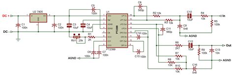
Here’s a basic analog audio delay circuit using a PT2399 digital delay IC:
Components
- PT2399 digital delay IC
- 10 kΩ potentiometer (delay time)
- 100 kΩ potentiometer (feedback)
- 10 kΩ potentiometer (mix)
- 100 nF ceramic capacitor
- 10 μF electrolytic capacitor
- 2x 1 kΩ resistors
- Audio input and output jacks
Schematic
                     +5V
                      |
                     |-|
                     | |
                     | | 10 kΩ (delay time)
                     | |
                     |-|
                      |
                     |-|
                     | |
Input >----|---------| | PT2399
           |         | |
           |         |-|
           |          |
           |         |-|
           |         | |
           |----||---| | 100 nF
                     | |
                     |-|
                      |
                     |-|
                     | |
                     | | 100 kΩ (feedback)
                     | |
                     |-|
                      |
                     |-|
                     | |
                     | | 10 kΩ (mix)
                     | |
                     |-|
                      |
                      >-----|| 10 μF >---- Output
Instructions
-
Connect the PT2399 IC as shown in the schematic, with the delay time, feedback, and mix potentiometers controlling the respective parameters.
-
The 100 nF capacitor sets the minimum delay time, while the 10 μF capacitor AC-couples the output.
-
The 1 kΩ resistors provide current limiting and help to isolate the input and output stages.
-
Power the circuit with a clean 5V supply, and connect the input and output to your audio system.
-
Adjust the potentiometers to dial in the desired delay effect.
This simple circuit provides a basic platform for experimenting with audio delay effects. More advanced designs can incorporate additional features like tap tempo control, stereo outputs, and modulation capabilities.
FAQ
What is the difference between echo and reverberation?
Echo is a distinct, repeating delay effect, while reverberation is a more complex, diffuse effect that simulates the natural acoustic reflections in a space. Echo is characterized by clear, discrete repeats, while reverb produces a smooth, continuous decay.
How do I choose the right delay time for my application?
The ideal delay time depends on the tempo, rhythm, and desired effect in your audio material. As a general rule, shorter delay times (50-200 ms) are good for slapback echoes and rhythmic effects, while longer times (200-800 ms) are better for spacious, atmospheric effects. Experiment with different settings to find the sweet spot for your particular application.
Can I use multiple delay effects simultaneously?
Yes, many audio systems and DAWs allow you to chain multiple delay effects in series or parallel. This can create complex, layered effects with unique rhythmic and spatial characteristics. However, be careful not to overdo it, as too many delays can quickly muddy the sound and create confusion in the mix.
How do I avoid unwanted feedback and oscillation in my delay circuit?
To minimize the risk of unwanted feedback and oscillation, keep the feedback level below the point of self-oscillation (usually around 80-90% for most delay circuits). Additionally, use a limiter or compressor after the delay circuit to catch any stray peaks and prevent runaway feedback. Proper gain staging and EQ can also help to tame problematic frequencies and maintain a clean, stable delay effect.
What are some creative ways to use delay effects in my audio projects?
- Create rhythmic echo patterns by setting the delay time to match the tempo of your audio material
- Use short, modulated delays to add thickness and movement to instruments or vocals
- Automate the delay parameters over time to create evolving, dynamic effects
- Experiment with unconventional delay times and feedback settings to create unique, abstract textures
- Process the delayed signal with additional effects like distortion, filtering, or reverb for even more creative possibilities
By understanding the fundamentals of audio delay circuits and experimenting with different settings and techniques, you can unlock a world of creative potential for your audio projects. Whether you’re working with analog hardware or digital software, delay effects are an essential tool for any audio engineer or producer looking to add depth, space, and character to their sound.


Leave a Reply