What is an Arduino Solar Charger?
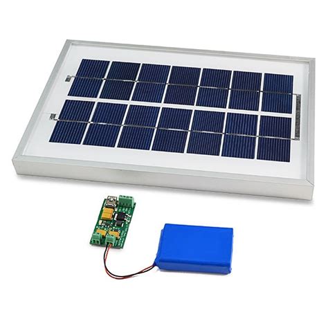
An Arduino solar charger is a DIY system that uses solar panels to convert sunlight into electricity, which is then regulated by an Arduino microcontroller to safely charge batteries or power devices. The key components include:
- Solar panel(s) to collect solar energy
- Arduino board to control the charging process
- Charge controller circuit to regulate voltage and current
- Rechargeable battery to store the harvested energy
- USB or other output to power devices
By combining these elements, you can create a portable, eco-friendly charging solution for small electronics like phones, tablets, Arduino projects, and more.
Why Build an Arduino Solar Charger?
There are several compelling reasons to create your own Arduino solar charging system:
-
Sustainability: Solar energy is clean, renewable, and abundant. By using the sun to power your devices, you reduce reliance on the grid and minimize your environmental impact.
-
Portability: A well-designed solar charger is compact and self-contained, allowing you to keep your gadgets charged on the go, even in remote locations without access to wall outlets.
-
Education: Building a solar charger is a great way to learn about electronics, solar power, battery charging, and Arduino programming. It’s a rewarding project for STEM students, hobbyists and makers.
-
Customization: With an Arduino at the heart of your system, you have flexibility to tailor the charger to your needs, add features like charging status displays, and integrate it with other projects.
-
Cost-effectiveness: While there is an initial investment in parts, a DIY charger can pay for itself over time by reducing your energy bills and providing free power indefinitely.

Key Components and Features to Consider
To build a successful Arduino solar charger, you’ll need to select the right components and plan out your system. Here are the key considerations:
Solar Panels
The solar panel is the powerhouse of your charger, capturing photons and converting them to electrical energy. Key factors include:
-
Power output: Measured in watts (W), this indicates the maximum power the panel can produce under ideal conditions. Higher wattage means faster charging but also larger size and cost. A 10W-20W panel is suitable for most small devices.
-
Voltage: Panels are rated for a specific voltage, typically 6V, 12V or 24V. Choose one that matches your battery voltage.
-
Size and weight: For portability, look for compact, lightweight panels with high efficiency. Mono-crystalline panels tend to perform best.
-
Weatherproofing: Outdoor-rated panels are built to withstand moisture and temperature extremes. Consider a ruggedized panel for camping and adventure use.
Arduino Board
The Arduino acts as the “brain” of the solar charger, using various inputs to monitor the charging process and control the flow of power. Some popular options:
| Board | Key Features | Cost |
|---|---|---|
| Arduino Uno | Beginner-friendly, plenty of I/O pins | $20-$30 |
| Arduino Nano | Compact size, low-power consumption | $15-$25 |
| Arduino Pro Mini | Smallest option, ideal for portable designs | $10-$15 |
For solar charging, you’ll primarily use analog input pins to measure voltages, and PWM output pins to control the charger circuit. More advanced boards like the Arduino MKR series offer additional features but may be overkill for this application.
Charge Controller
To safely and efficiently charge your battery from the solar panel, you need a charge controller circuit. This regulates the voltage and current to prevent overcharging and other hazards. Options include:
-
Linear regulator: Simple but inefficient, converts excess voltage to heat. Example: LM7805 for 5V output.
-
Switching regulator: More complex but efficient, turns excess power on/off rapidly. Example: LM2596 buck converter.
-
MPPT controller: Maximum Power Point Tracking, extracts the most power possible from the panel. Example: SPV1040 IC.
For most small-scale Arduino chargers, a basic switching regulator is a good balance of performance and simplicity. Aim for an output voltage slightly higher than your battery’s maximum charge voltage.
Battery
The battery stores energy from the solar panel for later use. Rechargeable lithium-ion and lead-acid batteries are common in solar projects. Factors to consider:
-
Chemistry: Li-ion batteries are lightweight and efficient but expensive. Lead-acid are cheaper and more durable. For Arduino projects, 18650 Li-ion cells are a popular choice.
-
Voltage: Common options are 3.7V (single Li-ion), 7.4V (2S Li-ion pack), and 12V (lead-acid or 3S Li-ion). Higher voltage means more power storage.
-
Capacity: Measured in milliamp-hours (mAh) or amp-hours (Ah), indicates how long the battery can power your device. A 2000mAh battery can supply 2000mA for one hour, 200mA for 10 hours, etc.
-
Protection circuit: Essential for Li-ion batteries to prevent over-charge, over-discharge, and short circuit damage. Some batteries have this built-in.
Select a battery that fits your voltage needs and offers sufficient capacity to power your device through periods of low sunlight.
Connectors and Peripherals
To make your solar charger user-friendly and informative, consider additional components like:
-
USB output: A female USB port allows you to plug in standard USB charging cables. You’ll need a voltage regulator to ensure a steady 5V output.
-
Charge status LEDs: Use the Arduino to control LEDs that indicate battery level, charging status, errors, etc.
-
Buttons and switches: Allow the user to turn the charger on/off or select different modes.
-
LCD display: For more detailed info like voltage readings, current flow, etc. Requires more Arduino pins and programming.
-
Moisture sensors: Can be used to detect rain and automatically disconnect the panel to prevent damage.
With these components in hand, you’re ready to start designing your Arduino solar charger system.

Designing the Solar Charger Circuit
The specifics of your charger circuitry will depend on your choice of components, but here’s a general outline:
Solar Panel -> Charge Controller -> Battery -> Output Regulator -> USB Port
                       |                           |
                       ˅                           ˅
                    Arduino                 Status LEDs/Display
Some key design tips:
- Use Schottky diodes to prevent reverse current flow from the battery to the solar panel when the panel voltage drops.
- Include voltage dividers on Arduino analog inputs to scale the measurable range.
- Use MOSFET transistors to switch loads on/off based on Arduino output pins.
- Add fuses or PTC resettable fuses to protect against overcurrent conditions.
- Include decoupling capacitors to smooth out noise on the power rails.
You can find many example schematics and wiring diagrams online for Arduino solar chargers. Use these as a starting point and adapt them to your needs.

Programming the Arduino
With the hardware in place, it’s time to write the Arduino sketch that will control your solar charger. The exact code will vary based on your setup, but here are the key tasks to accomplish:
-
Read solar panel voltage: Use
analogRead()on a voltage divider input to measure the panel output. Scale the 0-1023 reading to the actual voltage range. -
Read battery voltage: Similarly monitor the battery voltage to detect when it’s full or empty.
-
Control the charge controller: Use
analogWrite()ordigitalWrite()to adjust the PWM duty cycle or on/off state of your charge controller based on the measured voltages. Implement safety cutoffs to prevent overcharge/discharge. -
Display charge status: Update LEDs, LCD, or other indicators based on the system state (charging, full, error, etc.)
-
Manage output: Enable/disable the output to the USB port or other loads as needed to protect the battery.
-
Add energy saving features: Put the Arduino into sleep mode when not actively charging to conserve power. Wake up periodically to check the panel voltage.
Here’s a simplified example sketch for a charger using a switching regulator and 1S Li-ion battery:
#define SOLAR_VOLTAGE_PIN A0
#define BATTERY_VOLTAGE_PIN A1
#define CHARGE_ENABLE_PIN 9
#define RED_LED 6
#define GREEN_LED 5

float solarVoltage = 0;
float batteryVoltage = 0;

void setup() {
  pinMode(SOLAR_VOLTAGE_PIN, INPUT);
  pinMode(BATTERY_VOLTAGE_PIN, INPUT);
  pinMode(CHARGE_ENABLE_PIN, OUTPUT);
  pinMode(RED_LED, OUTPUT);
  pinMode(GREEN_LED, OUTPUT);
}

void loop() {
  solarVoltage = analogRead(SOLAR_VOLTAGE_PIN) * (5.0 / 1023.0) * 5.0;
  batteryVoltage = analogRead(BATTERY_VOLTAGE_PIN) * (5.0 / 1023.0) * 2.0;

  if (solarVoltage > 5.0 && batteryVoltage < 4.2) {
    digitalWrite(CHARGE_ENABLE_PIN, HIGH);
    digitalWrite(RED_LED, HIGH);
    digitalWrite(GREEN_LED, LOW);
  } else {
    digitalWrite(CHARGE_ENABLE_PIN, LOW);
    digitalWrite(RED_LED, LOW);
    if (batteryVoltage >= 4.2) {
      digitalWrite(GREEN_LED, HIGH);
    } else {
      digitalWrite(GREEN_LED, LOW);
    }
  }

  delay(1000);
}
This sketch reads the solar and battery voltages, enables the charger if the solar voltage exceeds 5V and the battery isn’t full, and indicates the charging status with red and green LEDs. It’s a basic starting point that you can expand with more features.
Testing and Troubleshooting
Before relying on your solar charger in the field, thoroughly test it to ensure proper operation and safety. Some key things to check:
- Verify that the solar panel is providing the expected voltage under direct sunlight.
- Confirm that the battery charges to its maximum voltage and the charger shuts off appropriately.
- Test the output voltage and current to your devices, ensuring it stays within USB specs (5V, <2.4A).
- Monitor the system over extended periods to check for overheating, voltage drops, or other issues.
- Validate that the Arduino sleeps and wakes up properly to conserve energy.
If you encounter problems, use a multimeter and the Arduino’s serial monitor to diagnose where the issue lies. Common pitfalls include:
- Incorrect wiring or loose connections
- Mismatched component voltages or current ratings
- Lack of proper regulation or protection circuitry
- Code bugs or inconsistent state management
- Insufficient solar panel power in low-light conditions
By methodically testing each part of the system and making incremental improvements, you can create a robust and reliable solar charger.
Conclusion
An Arduino-based solar charger is a powerful tool for keeping your devices powered up with clean, free energy from the sun. By understanding the key components, design considerations, and programming principles involved, you can create a custom charger that meets your specific needs.
Remember, solar charging is all about balance and efficiency. Choose components that work well together, optimize your code for low power consumption, and don’t forget to prioritize safety with proper circuit protection.
With a bit of know-how and tinkering, you can build a versatile, sustainable charging solution that will keep your projects running smoothly, wherever your adventures may take you. So get out there, soak up some sun, and happy charging!
Frequently Asked Questions
What size solar panel do I need to charge my device?
The size of the solar panel depends on several factors, including:
- The power consumption of your device
- The efficiency of your charger circuit
- The amount of sunlight available in your location
- How quickly you need to charge the device
As a general rule of thumb, a 10W-20W panel is sufficient to charge most smartphones and small devices within a few hours, assuming good sunlight. For larger devices like tablets or power banks, you may want a panel in the 20W-50W range. It’s better to oversize the panel slightly than to undersize it, as the charge controller will regulate the power flow to prevent overcharging.
Can I use any type of rechargeable battery with a solar charger?
In theory, you can use any type of rechargeable battery with a solar charging system, as long as you have the appropriate charge control and regulation circuitry. However, some battery chemistries are better suited to solar applications than others.
Lithium-ion batteries, particularly 18650 cells, are a popular choice for small-scale solar projects due to their high energy density, low self-discharge rate, and ability to handle many charge cycles. They do require careful charge management to prevent safety issues.
Lead-acid batteries are another common option, especially for larger systems. They’re inexpensive and robust, but heavy and less efficient than Li-ion.
Nickel-Metal Hydride (NiMH) and Nickel-Cadmium (NiCd) batteries can also work, but they have lower energy density and may suffer from the “memory effect” if not fully discharged before recharging.
Ultimately, the best battery choice depends on your specific application, budget, and performance needs.
How do I know when the battery is fully charged?
The Arduino can detect when the battery has reached its maximum charge voltage and signal the charge controller to stop charging. For most Li-ion batteries, the full charge voltage is around 4.2V per cell. So a 1S (single cell) Li-ion battery would be considered full at 4.2V, while a 2S (two cell) pack would be full at 8.4V.
In your Arduino sketch, you can use the analogRead() function to measure the battery voltage (scaled down with a voltage divider to fit within the 0-5V range of the analog inputs). When this reading corresponds to the full voltage, you can set a flag or directly disable the charge controller.
It’s a good idea to include some hysteresis in your voltage thresholds, so that the charger doesn’t rapidly turn on and off if the battery voltage is hovering right at the full level. For instance, you might stop charging at 4.2V but not re-enable it until the battery drops to 4.1V.
You can also indicate the charge status to the user with LEDs or other displays, so they know when the battery is topped off and ready to use.
What happens if the solar panel is shaded or it’s a cloudy day?
If the solar panel is partially shaded or the sunlight is less intense due to clouds or other obstructions, the panel will produce less power. In some cases, it may not generate enough voltage to charge the battery at all.
A well-designed solar charger should be able to handle these low-light conditions gracefully. The charge controller will simply draw less current from the panel and charge the battery more slowly. As long as the battery doesn’t drain faster than the panel can recharge it, the system will continue to function, just at a reduced capacity.
In your Arduino code, you can monitor the solar panel voltage and adjust the charger behavior accordingly. If the voltage drops below a certain threshold (say, 5V for a 6V panel), you might disable the charger entirely to prevent backfeeding from the battery to the panel. You could also display a warning to the user that charging is paused due to insufficient sunlight.
If you need to ensure a consistent charge rate regardless of weather conditions, you can oversize your solar panel to account for the worst-case scenario, or include a backup charging option like a USB input port.
Can I use this solar charger with other Arduino projects?
Absolutely! One of the great things about an Arduino-based solar charger is its versatility. With a few modifications, you can integrate it with all sorts of other Arduino projects.
For instance, you could use the solar charger to power a remote sensor station, an automated garden watering system, or a portable weather monitor. By connecting the charger’s output to the VIN pin of your Arduino, you can run your project directly from the battery, and the solar panel will keep it charged up.
You can also use the Arduino in your solar charger to control other peripherals, like a battery level display, a solar tracking motor, or a wireless data logging module. The possibilities are endless!
Just be sure to consider the power requirements of your additional components and size your solar panel and battery accordingly. And don’t forget to adapt your code to manage the energy flows and sleep/wake cycles of the entire system.
With a bit of creativity and experimentation, you can create some truly impressive and practical solar-powered Arduino projects. So go ahead and let your imagination run wild – the sun’s the limit!


Leave a Reply