Introduction to the Arduino Pro Micro
The Arduino Pro Micro is a microcontroller board designed and manufactured by SparkFun Electronics. It is based on the ATmega32U4 chip, which combines a microcontroller and a USB interface in a single package. The board is compatible with the Arduino IDE and can be programmed using the familiar Arduino syntax.
Key Features of the Arduino Pro Micro
- Microcontroller: ATmega32U4
- Operating Voltage: 5V
- Input Voltage: 5-12V
- Digital I/O Pins: 12
- PWM Channels: 5
- Analog Input Pins: 4
- Flash Memory: 32KB
- SRAM: 2.5KB
- EEPROM: 1KB
- Clock Speed: 16MHz
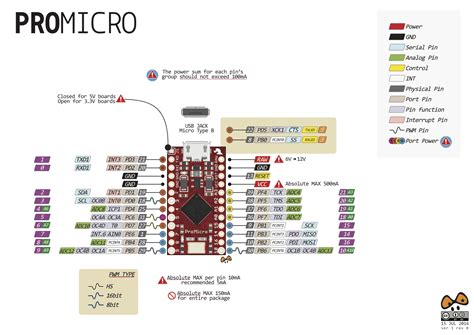
Arduino Pro Micro Pinout Diagram
To effectively use the Arduino Pro Micro, it’s crucial to understand its pinout. The following table provides an overview of the Pro Micro’s pins and their functions:
| Pin | Function | Description |
|---|---|---|
| RAW | Power Input | Unregulated power input (5-12V) |
| GND | Ground | Common ground |
| RST | Reset | Reset pin for the microcontroller |
| VCC | Regulated Power Output | 5V regulated power output |
| P21 | Digital I/O | General-purpose digital I/O pin |
| P20 | Digital I/O | General-purpose digital I/O pin |
| P19 | Digital I/O | General-purpose digital I/O pin |
| P18 | Digital I/O | General-purpose digital I/O pin |
| P15 | Digital I/O | General-purpose digital I/O pin |
| P14 | Digital I/O | General-purpose digital I/O pin |
| P16 | Digital I/O | General-purpose digital I/O pin |
| P10 | Digital I/O | General-purpose digital I/O pin |
| P1 | Digital I/O | General-purpose digital I/O pin |
| P0 | Digital I/O | General-purpose digital I/O pin |
| P2 | Digital I/O | General-purpose digital I/O pin |
| P3 | Digital I/O | General-purpose digital I/O pin |
| P4 | Digital I/O | General-purpose digital I/O pin |
| P5 | Digital I/O | General-purpose digital I/O pin |
| P6 | Digital I/O | General-purpose digital I/O pin |
| P7 | Digital I/O | General-purpose digital I/O pin |
| P8 | Digital I/O | General-purpose digital I/O pin |
| P9 | Digital I/O | General-purpose digital I/O pin |
Power Pins
The Arduino Pro Micro has two power-related pins: RAW and VCC. The RAW pin is used to supply unregulated power to the board, typically between 5V and 12V. The VCC pin provides a regulated 5V output, which can be used to power other components connected to the Pro Micro.
Digital I/O Pins
The Pro Micro features 12 digital I/O pins, labeled P0 to P21 (with some gaps in the numbering). These pins can be configured as either inputs or outputs, allowing you to connect various sensors, actuators, and other components to the board. Some of these pins have additional functionality, such as PWM (Pulse Width Modulation) or interrupt capabilities.
Analog Input Pins
The Arduino Pro Micro has 4 analog input pins, labeled A0 to A3. These pins can read analog voltages between 0V and 5V, making them suitable for connecting analog sensors like potentiometers, light sensors, or temperature sensors. The analog inputs have a resolution of 10 bits, meaning they can distinguish between 1024 different voltage levels.
Serial Communication Pins
The Pro Micro supports serial communication through its USB interface, which is connected to the ATmega32U4’s hardware UART (Universal Asynchronous Receiver/Transmitter). This allows the board to communicate with a computer or other devices using a virtual serial port. The serial communication pins are not accessible on the board itself but can be used through the USB connection.
I2C and SPI Pins
The Arduino Pro Micro supports I2C (Inter-Integrated Circuit) and SPI (Serial Peripheral Interface) communication protocols. These protocols allow the board to communicate with various external devices, such as sensors, displays, or memory modules. The I2C pins are labeled SDA (data) and SCL (clock), while the SPI pins are labeled MISO (Master In Slave Out), MOSI (Master Out Slave In), and SCK (Serial Clock).

Using the Arduino Pro Micro
Now that you understand the Arduino Pro Micro pinout, let’s explore how to use the board in your projects.
Programming the Pro Micro
To program the Arduino Pro Micro, you’ll need to install the Arduino IDE on your computer. The Pro Micro uses a different bootloader than standard Arduino boards, so you’ll need to follow these steps to set up the IDE:
- Open the Arduino IDE.
- Go to “Tools” > “Board” and select “Arduino Leonardo” (the Pro Micro is compatible with the Leonardo board).
- Connect the Pro Micro to your computer using a USB cable.
- Go to “Tools” > “Port” and select the port that corresponds to your Pro Micro.
- Write your Arduino sketch and click the “Upload” button to program the board.
Connecting Components to the Pro Micro
When connecting components to the Arduino Pro Micro, refer to the pinout diagram to identify the appropriate pins. Here are some common examples:
Connecting an LED
To connect an LED to the Pro Micro, follow these steps:
- Connect the anode (longer leg) of the LED to a digital I/O pin through a current-limiting resistor (typically 220Ω to 1kΩ).
- Connect the cathode (shorter leg) of the LED to the GND pin.
- In your Arduino sketch, set the digital pin as an output and use the
digitalWrite()function to control the LED.
const int ledPin = 10;

void setup() {
  pinMode(ledPin, OUTPUT);
}

void loop() {
  digitalWrite(ledPin, HIGH);
  delay(1000);
  digitalWrite(ledPin, LOW);
  delay(1000);
}
Connecting a Button
To connect a button to the Pro Micro, follow these steps:
- Connect one leg of the button to a digital I/O pin.
- Connect the other leg of the button to the GND pin.
- In your Arduino sketch, set the digital pin as an input with the internal pull-up resistor enabled using
pinMode(buttonPin, INPUT_PULLUP). - Use the
digitalRead()function to read the state of the button.
const int buttonPin = 9;

void setup() {
  pinMode(buttonPin, INPUT_PULLUP);
  Serial.begin(9600);
}

void loop() {
  int buttonState = digitalRead(buttonPin);
  Serial.println(buttonState);
  delay(100);
}
Connecting an Analog Sensor
To connect an analog sensor to the Pro Micro, follow these steps:
- Connect the sensor’s output pin to one of the analog input pins (A0 to A3).
- If required, connect the sensor’s power and ground pins to the VCC and GND pins, respectively.
- In your Arduino sketch, use the
analogRead()function to read the sensor value.
const int sensorPin = A0;

void setup() {
  Serial.begin(9600);
}

void loop() {
  int sensorValue = analogRead(sensorPin);
  Serial.println(sensorValue);
  delay(100);
}
Powering the Pro Micro
The Arduino Pro Micro can be powered in two ways:
- Through the USB connection: When connected to a computer or a USB power source, the Pro Micro can draw power directly from the USB port.
- Using an external power source: Connect a 5-12V power source to the RAW pin and GND. The on-board voltage regulator will provide a stable 5V output on the VCC pin.

Advanced Features of the Arduino Pro Micro
The Arduino Pro Micro offers several advanced features that can be utilized in more complex projects.
Interrupt Pins
Some of the digital I/O pins on the Pro Micro can be configured as interrupt pins. Interrupts allow the microcontroller to respond immediately to external events, such as a change in the state of a button or sensor. The Pro Micro has two external interrupt pins: P3 (INT0) and P2 (INT1). To use interrupts, attach an interrupt service routine (ISR) to the desired pin using the attachInterrupt() function.
const int interruptPin = 3;
volatile int counter = 0;

void setup() {
  pinMode(interruptPin, INPUT_PULLUP);
  attachInterrupt(digitalPinToInterrupt(interruptPin), increment, FALLING);
  Serial.begin(9600);
}

void loop() {
  Serial.println(counter);
  delay(1000);
}

void increment() {
  counter++;
}
Pulse Width Modulation (PWM)
The Arduino Pro Micro supports PWM on pins P5, P6, P9, P10, and P11. PWM allows you to generate analog-like signals using digital pins, which is useful for controlling the brightness of LEDs, the speed of motors, or the position of servos. To use PWM, call the analogWrite() function with a value between 0 and 255.
const int pwmPin = 9;

void setup() {
  pinMode(pwmPin, OUTPUT);
}

void loop() {
  for (int i = 0; i <= 255; i++) {
    analogWrite(pwmPin, i);
    delay(10);
  }
  for (int i = 255; i >= 0; i--) {
    analogWrite(pwmPin, i);
    delay(10);
  }
}
I2C and SPI Communication
The Arduino Pro Micro supports I2C and SPI communication, allowing it to interface with a wide range of external devices. To use I2C, connect the SDA and SCL pins to the corresponding pins on the external device and use the Wire library in your Arduino sketch. For SPI communication, connect the MISO, MOSI, and SCK pins to the external device and use the SPI library.
#include <Wire.h>

const int i2cAddress = 0x68;

void setup() {
  Wire.begin();
  Serial.begin(9600);
}

void loop() {
  Wire.beginTransmission(i2cAddress);
  Wire.write(0x00);
  Wire.endTransmission();
  Wire.requestFrom(i2cAddress, 1);
  if (Wire.available()) {
    int data = Wire.read();
    Serial.println(data);
  }
  delay(1000);
}

Frequently Asked Questions (FAQ)
-
Q: Can I use the Arduino Pro Micro with the Arduino IDE?
A: Yes, the Arduino Pro Micro is compatible with the Arduino IDE. However, you need to select the “Arduino Leonardo” board in the IDE, as the Pro Micro uses the same bootloader and configuration as the Leonardo. -
Q: What is the difference between the RAW and VCC pins on the Pro Micro?
A: The RAW pin is used to supply unregulated power (5-12V) to the Pro Micro, while the VCC pin provides a regulated 5V output. If you’re powering the board through the RAW pin, the on-board voltage regulator will convert the input voltage to a stable 5V on the VCC pin. -
Q: Can I use the Arduino Pro Micro for USB HID (Human Interface Device) projects?
A: Yes, the Arduino Pro Micro’s ATmega32U4 microcontroller has built-in USB capabilities, allowing it to emulate HID devices such as keyboards, mice, or game controllers. You can use libraries like “Keyboard” and “Mouse” to create custom HID projects. -
Q: How do I reset the Arduino Pro Micro?
A: The Pro Micro has a reset button on the board, which you can press to manually reset the microcontroller. Alternatively, you can connect the RST pin to the GND pin momentarily to trigger a reset. -
Q: What should I do if I encounter issues while uploading sketches to the Pro Micro?
A: If you experience problems uploading sketches to the Arduino Pro Micro, try the following: - Make sure you have selected the correct board (Arduino Leonardo) and port in the Arduino IDE.
- Press the reset button on the Pro Micro twice quickly to enter the bootloader mode, then try uploading the sketch again.
- Check your USB cable and connections to ensure they are secure and working properly.
Conclusion
The Arduino Pro Micro is a powerful and versatile microcontroller board that offers a wide range of features and capabilities in a compact form factor. By understanding the Arduino Pro Micro pinout and how to use its various pins and functions, you can create diverse projects ranging from simple LED controls to complex interactive devices.
Remember to refer to the pinout diagram when connecting components, and take advantage of the Pro Micro’s advanced features like interrupts, PWM, and communication protocols to enhance your projects. With its compatibility with the Arduino IDE and extensive online resources, the Arduino Pro Micro is an excellent choice for both beginners and experienced makers alike.


Leave a Reply