Introduction to Arduino Nano
The Arduino Nano is a compact, versatile, and popular microcontroller board based on the ATmega328P (Arduino Nano 3.x) or ATmega168 (Arduino Nano 2.x) chip. It offers similar functionality to the Arduino Uno but in a smaller form factor, making it ideal for projects with limited space requirements. The Arduino Nano is widely used by hobbyists, students, and professionals for various applications, including robotics, home automation, and embedded systems.
Key Features of Arduino Nano
- Microcontroller: ATmega328P (Arduino Nano 3.x) or ATmega168 (Arduino Nano 2.x)
- Operating Voltage: 5V
- Input Voltage (recommended): 7-12V
- Input Voltage (limits): 6-20V
- Digital I/O Pins: 14 (6 provide PWM output)
- Analog Input Pins: 8
- DC Current per I/O Pin: 40 mA
- Flash Memory: 32 KB (ATmega328P) or 16 KB (ATmega168)
- SRAM: 2 KB (ATmega328P) or 1 KB (ATmega168)
- EEPROM: 1 KB (ATmega328P) or 512 bytes (ATmega168)
- Clock Speed: 16 MHz
- Dimensions: 18 mm x 45 mm
- Weight: 7 g
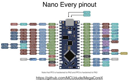
Arduino Nano Pinout
The Arduino Nano pinout consists of various pins that allow the microcontroller to interface with external components, sensors, and devices. Understanding the pinout is crucial for connecting peripherals and designing circuits effectively.
Digital I/O Pins
The Arduino Nano has 14 digital I/O pins, labeled D0 to D13. These pins can be used as either inputs or outputs, depending on the requirements of the project. Each pin can provide or sink a maximum current of 40 mA.
| Pin | Description |
|---|---|
| D0 | Digital I/O pin 0 (RX) |
| D1 | Digital I/O pin 1 (TX) |
| D2 | Digital I/O pin 2 |
| D3 | Digital I/O pin 3 (PWM) |
| D4 | Digital I/O pin 4 |
| D5 | Digital I/O pin 5 (PWM) |
| D6 | Digital I/O pin 6 (PWM) |
| D7 | Digital I/O pin 7 |
| D8 | Digital I/O pin 8 |
| D9 | Digital I/O pin 9 (PWM) |
| D10 | Digital I/O pin 10 (PWM) |
| D11 | Digital I/O pin 11 (PWM) |
| D12 | Digital I/O pin 12 |
| D13 | Digital I/O pin 13 (built-in LED) |
Analog Input Pins
The Arduino Nano features 8 analog input pins, labeled A0 to A7. These pins can read analog voltage values ranging from 0V to 5V, with a resolution of 10 bits (0-1023).
| Pin | Description |
|---|---|
| A0 | Analog input pin 0 |
| A1 | Analog input pin 1 |
| A2 | Analog input pin 2 |
| A3 | Analog input pin 3 |
| A4 | Analog input pin 4 |
| A5 | Analog input pin 5 |
| A6 | Analog input pin 6 |
| A7 | Analog input pin 7 |
Power and Ground Pins
The Arduino Nano has several power and ground pins that provide different voltage levels and serve as reference points for the microcontroller and connected components.
| Pin | Description |
|---|---|
| VIN | Input voltage (7-12V recommended) |
| 5V | Regulated 5V power supply |
| 3.3V | Regulated 3.3V power supply (max. 50 mA) |
| GND | Ground |
| RST | Reset pin (active low) |
| REF | Reference voltage for analog inputs |
Communication Pins
The Arduino Nano supports various communication protocols, including UART, I2C, and SPI. The following pins are used for communication:
| Pin | Description |
|---|---|
| D0 | UART RX |
| D1 | UART TX |
| A4 | I2C SDA (Serial Data) |
| A5 | I2C SCL (Serial Clock) |
| D10 | SPI SS (Slave Select) |
| D11 | SPI MOSI (Master Out Slave In) |
| D12 | SPI MISO (Master In Slave Out) |
| D13 | SPI SCK (Serial Clock) |

Programming the Arduino Nano
To program the Arduino Nano, you’ll need the Arduino Integrated Development Environment (IDE) and a USB cable to connect the board to your computer. The Arduino IDE provides a user-friendly interface for writing, compiling, and uploading code to the microcontroller.
Setting Up the Arduino IDE
- Download and install the Arduino IDE from the official Arduino website (https://www.arduino.cc/en/software).
- Launch the Arduino IDE.
- Go to “Tools” > “Board” and select “Arduino Nano” from the list of available boards.
- Choose the appropriate processor variant (ATmega328P or ATmega168) based on your Arduino Nano version.
- Select the correct serial port under “Tools” > “Port” to establish communication with the board.
Basic Arduino Sketch Structure
An Arduino sketch typically consists of two main functions: setup() and loop().
void setup() {
  // Code here runs once at the beginning
}

void loop() {
  // Code here runs repeatedly
}
The setup() function is called once when the Arduino Nano starts up or resets. It is used for initializing variables, setting pin modes, and configuring libraries.
The loop() function runs continuously after the setup() function completes. It contains the main logic of your program and executes repeatedly until the board is powered off or reset.
Digital I/O Example
Here’s a simple example that demonstrates how to use digital I/O pins on the Arduino Nano:
const int ledPin = 13;  // Built-in LED pin
const int buttonPin = 2;  // Push button pin

void setup() {
  pinMode(ledPin, OUTPUT);  // Set LED pin as output
  pinMode(buttonPin, INPUT_PULLUP);  // Set button pin as input with internal pull-up resistor
}

void loop() {
  int buttonState = digitalRead(buttonPin);  // Read the state of the button

  if (buttonState == LOW) {  // Button is pressed
    digitalWrite(ledPin, HIGH);  // Turn on the LED
  } else {
    digitalWrite(ledPin, LOW);  // Turn off the LED
  }
}
In this example, the built-in LED on pin 13 is controlled by the state of a push button connected to pin 2. When the button is pressed, the LED turns on; when the button is released, the LED turns off.
Analog Input Example
Here’s an example that demonstrates how to read analog values from an analog input pin on the Arduino Nano:
const int potPin = A0;  // Potentiometer pin

void setup() {
  Serial.begin(9600);  // Initialize serial communication
}

void loop() {
  int potValue = analogRead(potPin);  // Read the analog value from the potentiometer
  Serial.print("Potentiometer value: ");
  Serial.println(potValue);  // Print the value to the serial monitor
  delay(100);  // Delay for 100 milliseconds
}
In this example, a potentiometer is connected to analog input pin A0. The Arduino Nano reads the analog value from the potentiometer and sends it to the serial monitor for display. The delay() function is used to introduce a small pause between readings.

FAQ
1. What is the difference between the Arduino Nano and Arduino Uno?
The main differences between the Arduino Nano and Arduino Uno are their size and form factor. The Arduino Nano is much smaller and more compact than the Uno, making it suitable for projects with limited space. However, both boards offer similar functionality and have the same number of digital and analog pins.
2. Can I power the Arduino Nano directly from a battery?
Yes, you can power the Arduino Nano directly from a battery. The recommended input voltage range is 7-12V. If using a higher voltage battery, make sure to regulate the voltage down to a safe level before connecting it to the VIN pin.
3. How do I upload a sketch to the Arduino Nano?
To upload a sketch to the Arduino Nano, follow these steps:
- Connect the Arduino Nano to your computer using a USB cable.
- Open the Arduino IDE and ensure that the correct board and port are selected.
- Write or open your Arduino sketch.
- Click the “Upload” button in the Arduino IDE to compile and upload the sketch to the board.
4. Can I use external libraries with the Arduino Nano?
Yes, you can use external libraries with the Arduino Nano. The process is the same as with other Arduino boards. You can install libraries through the Arduino IDE’s Library Manager or manually by placing the library files in the appropriate directory.
5. What should I do if my Arduino Nano is not recognized by the computer?
If your Arduino Nano is not recognized by the computer, try the following:
- Ensure that the USB cable is securely connected to both the Arduino Nano and the computer.
- Check if the correct drivers are installed for the Arduino Nano. You may need to install the CH340 or FTDI drivers, depending on your board variant.
- Try using a different USB cable or USB port on your computer.
- Verify that the correct board and port are selected in the Arduino IDE.
- If the issue persists, try resetting the Arduino Nano by pressing the reset button on the board.

Conclusion
The Arduino Nano is a powerful and versatile microcontroller board that offers a compact form factor and extensive functionality. With its comprehensive pinout, including digital I/O pins, analog input pins, and communication interfaces, the Arduino Nano can be used in a wide range of projects and applications.
By understanding the Arduino Nano pinout and its specifications, you can effectively connect sensors, actuators, and other peripherals to create innovative and interactive projects. The Arduino IDE provides a user-friendly environment for programming the Arduino Nano, making it accessible to both beginners and experienced developers.
Whether you’re working on robotics, home automation, or embedded systems, the Arduino Nano is a reliable and affordable choice for bringing your ideas to life. With its extensive community support, extensive library ecosystem, and ease of use, the Arduino Nano empowers makers, students, and professionals to explore the world of microcontroller programming and electronics.


Leave a Reply