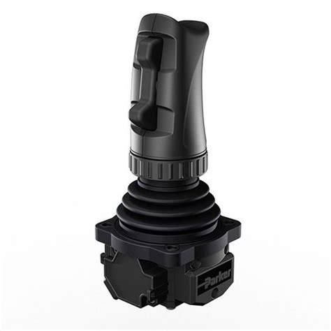
Introduction to Analog Joystick
An analog joystick is an input device that allows users to control various applications, robotics, and gaming systems by providing multi-directional input signals. It consists of a stick that can be tilted in any direction and typically includes a push-button functionality when the stick is pressed down. Analog joysticks are widely used in gaming controllers, industrial control panels, and robotics due to their intuitive and precise control capabilities.
How Analog Joysticks Work
Analog joysticks work by using potentiometers to measure the position of the joystick along two axes: X (horizontal) and Y (vertical). Potentiometers are variable resistors that change their resistance based on the position of the joystick. As the joystick is moved, the potentiometers’ resistance changes, resulting in varying voltage levels that can be read by a microcontroller or other processing unit.
The joystick typically has two potentiometers, one for each axis, positioned at a 90-degree angle to each other. The center position of the joystick represents a neutral state, where the output voltage is usually around half of the supply voltage (e.g., 2.5V for a 5V supply). As the joystick is moved away from the center, the output voltage increases or decreases accordingly.
In addition to the X and Y axes, many analog joysticks include a push-button switch that is activated when the joystick is pressed down. This button can be used for additional input, such as confirming a selection or triggering an action.
Advantages of Analog Joysticks
-
Intuitive control: Analog joysticks provide a natural and intuitive way to control various applications, as they mimic the directional input of real-world objects.
-
Precise input: The analog nature of joysticks allows for precise and smooth control, as opposed to the discrete input of digital buttons.
-
Multi-directional input: Analog joysticks can detect input in any direction, providing a greater range of control options compared to simple buttons or switches.
-
Versatility: Analog joysticks can be used in a wide range of applications, from gaming and robotics to industrial control panels and medical devices.
Analog Joystick Module
An analog joystick module is a self-contained unit that includes the joystick mechanism, potentiometers, and often a push-button switch. These modules are designed to be easily integrated into various projects and systems, providing a convenient way to add joystick functionality without the need for complex wiring or assembly.
Components of an Analog Joystick Module
A typical analog joystick module consists of the following components:
-
Joystick mechanism: The physical joystick that can be moved in various directions.
-
Potentiometers: Two potentiometers (variable resistors) that measure the position of the joystick along the X and Y axes.
-
Push-button switch: A switch that is activated when the joystick is pressed down.
-
Breakout pins: Pins that provide access to the potentiometers’ outputs, the push-button switch, and power supply connections.
-
PCB: A printed circuit board that holds all the components together and provides electrical connections.
Connecting an Analog Joystick Module
Analog joystick modules typically have the following pins:
-
VCC: Power supply pin, usually connected to a 5V source.
-
GND: Ground pin, connected to the common ground of the system.
-
VRx: Output pin for the X-axis potentiometer.
-
VRy: Output pin for the Y-axis potentiometer.
-
SW: Output pin for the push-button switch.
To connect an analog joystick module to a microcontroller, such as an Arduino, follow these steps:
-
Connect the VCC pin to the 5V pin on the Arduino.
-
Connect the GND pin to one of the GND pins on the Arduino.
-
Connect the VRx pin to an analog input pin on the Arduino (e.g., A0).
-
Connect the VRy pin to another analog input pin on the Arduino (e.g., A1).
-
Connect the SW pin to a digital input pin on the Arduino (e.g., D2).
Reading Analog Joystick Values
To read the values from an analog joystick module, you need to use the analog input pins on your microcontroller. In the case of an Arduino, you can use the analogRead() function to read the voltage levels on the VRx and VRy pins.
Here’s a simple Arduino sketch that demonstrates how to read the joystick values and print them to the serial monitor:
const int VRx = A0;
const int VRy = A1;
const int SW = 2;

void setup() {
  pinMode(VRx, INPUT);
  pinMode(VRy, INPUT);
  pinMode(SW, INPUT_PULLUP);
  Serial.begin(9600);
}

void loop() {
  int xValue = analogRead(VRx);
  int yValue = analogRead(VRy);
  int swValue = digitalRead(SW);

  Serial.print("X: ");
  Serial.print(xValue);
  Serial.print(" | Y: ");
  Serial.print(yValue);
  Serial.print(" | SW: ");
  Serial.println(swValue);

  delay(100);
}
In this sketch:
-
The
VRx,VRy, andSWconstants are defined to represent the analog and digital pins connected to the joystick module. -
In the
setup()function, theVRxandVRypins are set as inputs, and theSWpin is set as an input with the internal pull-up resistor enabled. The serial communication is also initialized. -
In the
loop()function, theanalogRead()function is used to read the voltage levels on theVRxandVRypins, while thedigitalRead()function is used to read the state of the push-button switch. -
The joystick values are then printed to the serial monitor, with a small delay between each reading.
When you run this sketch, you should see the joystick values being printed to the serial monitor. As you move the joystick, the X and Y values will change, and when you press the joystick down, the SW value will change from 1 to 0.
Calibrating an Analog Joystick Module
Due to manufacturing variations and component tolerances, the center position of an analog joystick may not always correspond to the exact middle of the voltage range. To ensure accurate and consistent readings, it’s a good practice to calibrate your analog joystick module.
Calibration involves determining the minimum, maximum, and center values for both the X and Y axes. Here’s a simple calibration procedure:
-
Connect your analog joystick module to your microcontroller as described earlier.
-
Upload a sketch that reads and prints the raw joystick values to the serial monitor, similar to the example provided in the previous section.
-
Move the joystick to the extreme positions (top, bottom, left, and right) and note down the minimum and maximum values for both the X and Y axes.
-
Move the joystick to the center position and note down the X and Y values.
-
Use the collected data to map the raw joystick values to a desired range (e.g., -100 to 100) in your final application.
Here’s an example of how you can map the raw joystick values to a calibrated range:
const int VRx = A0;
const int VRy = A1;

int xMin = 0;
int xMax = 1023;
int xCenter = 512;
int yMin = 0;
int yMax = 1023;
int yCenter = 512;

void setup() {
  pinMode(VRx, INPUT);
  pinMode(VRy, INPUT);
  Serial.begin(9600);
}

void loop() {
  int xRaw = analogRead(VRx);
  int yRaw = analogRead(VRy);

  int xMapped = map(xRaw, xMin, xMax, -100, 100);
  int yMapped = map(yRaw, yMin, yMax, -100, 100);

  xMapped = constrain(xMapped, -100, 100);
  yMapped = constrain(yMapped, -100, 100);

  Serial.print("X: ");
  Serial.print(xMapped);
  Serial.print(" | Y: ");
  Serial.println(yMapped);

  delay(100);
}
In this example:
-
The minimum, maximum, and center values for both axes are defined based on the data collected during the calibration process.
-
The
map()function is used to convert the raw joystick values to a calibrated range of -100 to 100. -
The
constrain()function ensures that the mapped values stay within the desired range. -
The calibrated joystick values are printed to the serial monitor.
By calibrating your analog joystick module, you can ensure that the center position corresponds to a value of 0, and the extreme positions correspond to the desired minimum and maximum values (e.g., -100 and 100).

Applications of Analog Joysticks
Analog joysticks are versatile input devices that can be used in a wide range of applications. Some common applications include:
Robotics
Analog joysticks are often used in robotics projects to control the movement and orientation of robots. By mapping the joystick’s X and Y values to the robot’s motor speeds or servo angles, you can create intuitive and responsive control systems.
For example, in a simple two-wheeled robot, the joystick’s Y-axis can be used to control the robot’s forward and backward motion, while the X-axis can be used to control the robot’s turning. Here’s a basic example of how this can be implemented using an Arduino:
const int VRx = A0;
const int VRy = A1;
const int motorL = 9;
const int motorR = 10;

void setup() {
  pinMode(VRx, INPUT);
  pinMode(VRy, INPUT);
  pinMode(motorL, OUTPUT);
  pinMode(motorR, OUTPUT);
}

void loop() {
  int xValue = analogRead(VRx);
  int yValue = analogRead(VRy);

  int leftSpeed = map(yValue, 0, 1023, -255, 255);
  int rightSpeed = map(yValue, 0, 1023, -255, 255);

  leftSpeed = constrain(leftSpeed, -255, 255);
  rightSpeed = constrain(rightSpeed, -255, 255);

  int steerValue = map(xValue, 0, 1023, -100, 100);
  leftSpeed += steerValue;
  rightSpeed -= steerValue;

  leftSpeed = constrain(leftSpeed, -255, 255);
  rightSpeed = constrain(rightSpeed, -255, 255);

  analogWrite(motorL, abs(leftSpeed));
  analogWrite(motorR, abs(rightSpeed));

  if (leftSpeed < 0) {
    // Reverse left motor direction
  } else {
    // Forward left motor direction
  }

  if (rightSpeed < 0) {
    // Reverse right motor direction
  } else {
    // Forward right motor direction
  }
}
In this example:
-
The joystick’s Y-axis value is mapped to the left and right motor speeds, allowing for forward and backward motion.
-
The joystick’s X-axis value is used to calculate a steering value, which is added to the left motor speed and subtracted from the right motor speed, allowing for turning.
-
The motor speeds are constrained to the valid PWM range (-255 to 255).
-
The
analogWrite()function is used to set the motor speeds, and additional logic is needed to control the motor direction based on the sign of the speed values.
This is just a basic example, and more advanced robotics projects may require additional features, such as acceleration control, dead zones, and multi-stage speed control.
Gaming Controllers
Analog joysticks are a key component in many gaming controllers, providing precise and intuitive control for various game genres, such as racing, flight simulators, and action games. In gaming controllers, analog joysticks are often used in combination with other input devices, such as buttons and triggers, to provide a wide range of control options.
When using an analog joystick module with a gaming controller, the joystick values can be read and processed by a microcontroller, which then communicates the input data to the gaming system via a suitable interface, such as USB or Bluetooth.
Here’s a simple example of how an analog joystick can be used as part of a custom gaming controller:
#include <Joystick.h>

const int VRx = A0;
const int VRy = A1;
const int SW = 2;

Joystick_ joystick;

void setup() {
  pinMode(VRx, INPUT);
  pinMode(VRy, INPUT);
  pinMode(SW, INPUT_PULLUP);

  joystick.begin();
}

void loop() {
  int xValue = analogRead(VRx);
  int yValue = analogRead(VRy);
  int swValue = digitalRead(SW);

  int xMapped = map(xValue, 0, 1023, -100, 100);
  int yMapped = map(yValue, 0, 1023, -100, 100);

  joystick.setXAxis(xMapped);
  joystick.setYAxis(yMapped);
  joystick.setButton(0, !swValue);

  delay(10);
}
In this example:
-
The
Joysticklibrary is used to create a virtual joystick that can be recognized by the gaming system. -
The joystick’s X and Y values are mapped to a range of -100 to 100 and sent to the gaming system using the
setXAxis()andsetYAxis()functions. -
The joystick’s push-button state is sent to the gaming system using the
setButton()function. -
The
delay()function is used to control the polling rate of the joystick.
Note that this example assumes you are using an Arduino-compatible board that supports the Joystick library, such as the Arduino Leonardo or Micro. For other gaming systems or interfaces, additional hardware and software configurations may be required.
Industrial Control Panels
Analog joysticks can be used in industrial control panels to provide intuitive and precise control over various processes and machinery. In this context, joysticks are often used to control the position, speed, or orientation of equipment, such as cranes, conveyor belts, or robotic arms.
When integrating an analog joystick module into an industrial control panel, it’s essential to consider factors such as the joystick’s durability, precision, and compatibility with the existing control system. Additionally, proper shielding and filtering may be necessary to protect the joystick from electromagnetic interference (EMI) and ensure reliable operation in industrial environments.
Here’s an example of how an analog joystick can be used to control a motorized linear actuator in an industrial setting:
const int VRx = A0;
const int actuatorPWM = 9;
const int actuatorDir = 8;

void setup() {
  pinMode(VRx, INPUT);
  pinMode(actuatorPWM, OUTPUT);
  pinMode(actuatorDir, OUTPUT);
}

void loop() {
  int xValue = analogRead(VRx);
  int speed = map(xValue, 0, 1023, -255, 255);

  if (speed > 0) {
    digitalWrite(actuatorDir, HIGH);
  } else {
    digitalWrite(actuatorDir, LOW);
  }

  analogWrite(actuatorPWM, abs(speed));
}
In this example:
-
The joystick’s X-axis value is used to control the speed and direction of the linear actuator.
-
The
map()function is used to convert the joystick value to a PWM range of -255 to 255. -
The actuator’s direction pin is set based on the sign of the speed value.
-
The
analogWrite()function is used to set the actuator’s speed using PWM.
This is a simplified example, and in practice, additional safety features, such as limit switches, emergency stops, and deadman switches, should be incorporated to ensure safe and reliable operation in an industrial setting.

Interfacing Analog Joysticks with Other Systems
In addition to the applications mentioned earlier, analog joysticks can be interfaced with various other systems and platforms to provide intuitive and precise control. Some common interfaces and platforms include:
Raspberry Pi
Analog joysticks can be easily interfaced with a Raspberry Pi using the GPIO pins and an analog-to-digital converter (ADC). The Raspberry Pi does not have built-in analog input pins, so an


Leave a Reply