Introduction
Printed circuit boards (PCBs) are an essential component of most modern electronic devices. They provide the physical platform to mount and interconnect electronic components using conductive copper traces etched from copper sheets laminated onto a non-conductive substrate. Traditional rigid PCBs serve most purposes well, but they lack flexibility and can be prone to cracking or breaking under bending or vibration stresses. This is where advanced flexible PCBs, commonly called flex PCBs or flex circuits, offer unique advantages for electronics design.
What are Flex PCBs?
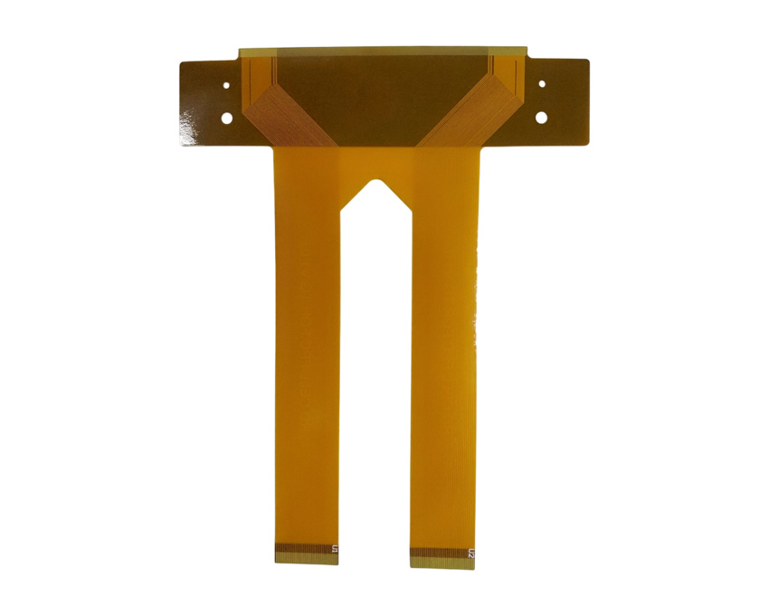
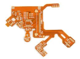
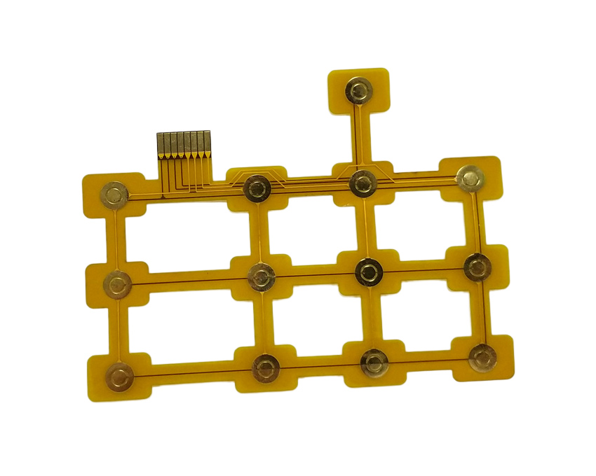
A flex PCB is a variant of a standard PCB in which the substrate is made of a flexible material such as polyimide or polyester rather than traditional rigid materials like FR-4. The conductive copper traces are also etched to deal with repeated bending cycles without cracking. This allows flex PCBs to be bent, folded, twisted, and formed into complex 3D shapes.
Flex PCBs provide several key advantages:
- Extremely thin and lightweight – Flex PCBs can be made with thicknesses down to 1 mil (25 microns) while maintaining signal integrity. This allows for integration into tight spaces and lightweight products.
- Highly customizable shapes – Flex PCBs can be shaped to fit unique geometries and enclosures that rigid boards cannot conform to.
- Dynamic flexing – They can dynamically flex and move during use to accommodate motion, vibration, and assembly.
- Improved reliability – The flexible construction absorms stresses and withstands vibration and impacts better than rigid PCBs.
- Design efficiency – Integrating interconnections into a single flex PCB eliminates the need for wiring harnesses and connectors.
Flex PCB Construction
Flex PCBs have a similar layered construction to rigid PCBs but use different flexible base materials. Common flex circuit substrates include:
- Polyimide (Kapton) – Most popular due to high flexibility, temperature resistance, and durability.
- Polyester (PET) – Lower cost but has less flexibility than polyimide.
- PEN – Provides higher temperature resistance but is less flexible.
The substrates are coated with an adhesive copper laminate layer. The desired conductive traces are then photolithographically etched from the copper layer. The resulting bare flexible PCB is usually reinforced with a backing stiffener on one or both sides to aid handling and assembly.
Types of Flex PCBs
There are several specific types of flex PCB constructions optimized for different applications:
Single Sided Flex Circuits
Consist of conductive traces on only one side of the substrate. Less expensive and ideal for simple low-density interconnection circuits.
Double Sided Flex Circuits
Have conductive layers on both sides of the substrate which are interconnected with plated through holes. Allows for more complex routing.
Multilayer Flex Circuits
Have 3 or more conductive routing layers separated by flexible dielectric materials. Permits very dense, complex interconnections for advanced designs.
Rigid-Flex PCBs
Combine standard rigid PCB sections with flexible PCB sections, connected by a section with both flexible and rigid layers. Used to transition from static boards to dynamic flexing interconnections.
Flex PCB vs Rigid PCB Tradeoffs
While flex PCBs provide unique advantages, traditional rigid PCB technologies still excel in several areas:
Flex PCB Advantages:
- Thinner, lighter weight construction
- Can conform to tight spaces and complex 3D geometries
- Withstands vibration, impacts, and repeated dynamic bending
- Simplifies cabling and wiring harnesses
- Generally better RF signal transmission properties
Rigid PCB Advantages:
- Lower material cost
- Simpler board handling and assembly
- Can support heavier and larger components
- Easier to mount heat sinks and cooling systems
- More suitable for high-volume production
Flex PCB Design Considerations
Designing a successful flex PCB requires considering a few key factors:
- Dynamic bending – Avoid sharp folds and account for flexing, twisting, and repeated cycling over the lifetime of the product.
- Component mounting – Minimal or lightweight surface mount parts only. No through-hole components.
- Routing – Trace geometries must accommodate extensive movement and bending. Avoid brittle right angles.
- Stiffening – Strategically locate stiffeners to manage bending in critical areas while allowing flexing where needed.
- ESD protection – Flex circuits can require additional ESD protection measures for sensitive signals.
- Layer stackup – For multilayer boards, ensure layer materials are compatible through all expected motion.
- Testing – Validate the design performs properly through the full range of bending motions.
Flex PCB Applications
Some of the many applications leveraging advanced flex PCB technology include:
- Wearable devices – Flex circuits integrated into bands, watches, and body sensors.
- Medical devices – Flexible sensors, circuits woven into clothing, swallowable health monitors.
- Consumer electronics – Cell phones, display assemblies, cameras, and charging cables.
- Automotive – Flexible interconnections for dynamic components in modern auto electronics.
- Aerospace – Used extensively in guidance systems and other space electronics where size, weight, and reliability are critical.
- Industrial electronics – Flexible interconnects for machinery, instrumentation, automation systems.
Flex PCB Assembly
Assembling components onto flex PCBs requires specialized approaches:
- Components must be surface-mount only, as through-hole parts cannot be reliably mounted to pliable boards.
- Adhesives are often required to bond components and manage stresses from flexing.
- Careful handling is required as flex circuits can be easily damaged if overstressed or bent excessively.
- Robotic pick-and-place assembly is preferred over manual assembly for reliability and precision.
- Electrical testing requires fixtures to simulate the completed shape and dynamic bending motions.
Leading Flex PCB Manufacturers
Some of the top manufacturers leading flex PCB technology and capabilities include:
- Minco – Offering design, prototyping and manufacturing of complex flex circuits for over 50 years.
- All Flex – Specializes in ultra-thin polyimide flex circuits as thin as .001 inch (.025 mm).
- Flex – A global flex PCB producer with over a dozen specialized factories worldwide.
- AT&S – An Austrian company focused on high-density interconnect and rigid-flex boards.
- TTM Technologies – A leader in complex multilayer flex and rigid-flex PCB solutions.
- Advanced Circuits – Quick-turn prototyping and production of rigid, flex, and rigid-flex designs.
The Future of Flex PCBs
Flex PCB technology will continue advancing to enable electronics innovation across industries. Key trends include:
- Expanding into new applications – Flex circuits open new possibilities in medical devices, wearables, robotics, and other emerging industries.
- Denser interconnections – Stacked microvia structures and advanced flexible materials allow for increasing circuit density.
- Higher operating frequencies – New materials and constructions better support higher-speed signals up to mmWave frequencies.
- Improved manufacturing – Processes like laser direct structuring allow complex flex board mass production.
- Embedding actives – Embedding bare die components into flex layers Integrated EMI shielding – Built-in shielding films and coatings.
Flex PCBs have proven extremely valuable where reliability, space, weight, and flexibility matter most. As long as electronics become smaller, lighter, and more robust, flex circuits will offer an indispensable solution.
Frequently Asked Questions
Q: What are the key benefits of flex PCBs?
A: The main benefits of flex PCBs are their extremely thin profile, light weight, ability to conform to complex shapes, dynamic flexing capability, and improved reliability under vibration or impacts. They can integrate interconnections in tight spaces where rigid boards won’t fit.
Q: What are some typical applications of flex circuits?
A: Typical applications that leverage the advantages of flex PCBs include wearable electronics, medical devices, consumer electronics, automotive electronics, aerospace avionics, robotics, IoT devices, and military electronics. Any application where size, weight, or flexibility are critical requirements.
Q: How are components assembled onto a flex PCB?
A: Only surface mount components can be reliably assembled onto flex PCBs. Through-hole parts are not suitable for flexible boards. Adhesives are often used to bond components and manage stresses. Automated pick-and-place assembly is preferred.
Q: What are some considerations when laying out a flex PCB design?
A: Important flex PCB layout considerations include managing dynamic bending, minimizing rigid sections, using flexible component packages, eliminating right angle trace geometries, strategic stiffener placement, and designing testability for flexed states.
Q: How are flex PCBs different from rigid PCBs?
A: The main differences are the flexible substrate material, ability to dynamically bend and flex, lighter weight, potential for much thinner constructions, improved resistance to vibration, and the inability to support through-hole components or some mounting techniques. Tradeoffs exist between both technologies.


Leave a Reply