Introduction to the ACS712 Current Sensor
The ACS712 is a popular Hall effect-based linear current sensor IC that can accurately measure AC or DC electrical current. It outputs an analog voltage proportional to the current flowing through its conduction path. The ACS712 is available in 3 different models with different current measurement ranges:
| ACS712 Model | Current Range | Sensitivity |
|---|---|---|
| ACS712ELCTR-05B-T | -5A to +5A | 185 mV/A |
| ACS712ELCTR-20A-T | -20A to +20A | 100 mV/A |
| ACS712ELCTR-30A-T | -30A to +30A | 66 mV/A |
The ACS712 operates from a 5V supply, has a low-resistance conductive path of 1.2mΩ, and provides electrical isolation up to 2.1kVRMS between the current path and the sensor leads. This allows it to be used in applications requiring electrical isolation without using optoisolators or other isolation techniques.
Key Features of the ACS712
- Hall effect-based linear current sensor
- Provides electrical isolation between current path and sensor
- 5V single supply operation
- 1.2mΩ internal conductor resistance
- 2.1kVRMS minimum isolation voltage
- 80kHz bandwidth
- Total output error of ±1.5% at TA = 25°C
- Nearly zero magnetic hysteresis
- Ratiometric output from supply voltage
- Factory-trimmed for accuracy
- Extremely stable output offset voltage
- Small SOP-8 package
How the ACS712 Current Sensor Works
The ACS712 works on the principle of the Hall effect. When a current-carrying conductor is placed in a magnetic field perpendicular to the current flow, a voltage is generated across the conductor at a right angle to both the current and magnetic field. This voltage is known as the Hall voltage.
In the ACS712, a precise, low-offset, linear Hall circuit with a copper conduction path is located near the surface of the die. Applied current flowing through the copper conduction path generates a magnetic field which is sensed by the Hall IC and converted into a proportional voltage.
The voltage output from the Hall IC is conditioned and amplified to provide a voltage output that is proportional to the applied current. The internal resistance of the copper conductor is extremely low (1.2 mΩ typical), so the ACS712 can be used in low-loss current sensing applications.
Functional Block Diagram
Here is a functional block diagram showing the internal workings of the ACS712:
The key components are:
- Copper conduction path
- Hall IC
- Signal conditioning and amplification circuitry
- Filter capacitor for stability
- Voltage regulator for 5V operation
When current flows through the copper conduction path, it generates a magnetic field that is detected by the Hall IC. The Hall IC outputs a voltage proportional to the magnetic field strength. This voltage is conditioned, amplified, and filtered to provide a clean analog voltage output that is proportional to the applied current.

Electrical Characteristics of the ACS712
The key electrical characteristics of the ACS712 are summarized in this table:
| Parameter | Value |
|---|---|
| Supply Voltage | 5V |
| Supply Current | 10 mA |
| Zero Current Output Voltage | VCC / 2 |
| Output Sensitivity | See table below |
| Bandwidth | 80 kHz |
| Total Output Error | ±1.5% at 25°C |
| Output Resistance | 1.2 mΩ |
The output sensitivity varies based on the current range of the specific ACS712 model:
| ACS712 Model | Sensitivity |
|---|---|
| ACS712-05B | 185 mV/A |
| ACS712-20A | 100 mV/A |
| ACS712-30A | 66 mV/A |
At zero current, the output of the ACS712 is VCC / 2. For example, with a 5V supply, the output is 2.5V at zero current. As the current increases, the output voltage rises above 2.5V. Conversely, as current flows in the opposite direction, the output drops below 2.5V.
The bandwidth of the ACS712 is 80 kHz, meaning it can accurately measure AC currents up to this frequency. The total output error is ±1.5% at room temperature.
Transfer Function
The transfer function of the ACS712 relates the output voltage to the applied current. It takes the following form:
V_OUT = (I_P ✕ Sensitivity) + V_CC/2
Where:
– V_OUT is the output voltage in volts
– I_P is the applied current in amps
– Sensitivity is the output sensitivity in V/A
– V_CC is the supply voltage in volts
For example, for an ACS712-20A with 100 mV/A sensitivity and a 5V supply:
– At 0A, V_OUT = (0 ✕ 0.1) + 5/2 = 2.5V
– At +20A, V_OUT = (20 ✕ 0.1) + 2.5 = 4.5V
– At -20A, V_OUT = (-20 ✕ 0.1) + 2.5 = 0.5V
So the full-scale output ranges from 0.5V at -20A to 4.5V at +20A.

Using the ACS712 with a Microcontroller
The analog output of the ACS712 can be easily read by an analog-to-digital converter (ADC) input of a microcontroller like an Arduino. The steps are:
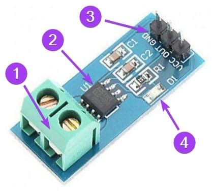
- Connect VCC and GND of the ACS712 to the 5V and GND pins of the Arduino.
- Connect the OUT pin of the ACS712 to an analog input pin on the Arduino.
- In your sketch, read the analog voltage using analogRead().
- Convert the ADC reading to voltage.
- Subtract VCC/2 to get a signed voltage relative to zero current.
- Divide by the sensitivity to convert voltage to current.
Here’s some sample Arduino code:
const int currentSensorPin = A0;
const float sensitivity = 0.1; // 100mV/A for ACS712-20A
const float vcc = 5.0;
const float vref = vcc / 2;

void setup() {
  Serial.begin(9600);
}

void loop() {
  int adcValue = analogRead(currentSensorPin);
  float voltage = adcValue * (vcc / 1024.0);
  float current = (voltage - vref) / sensitivity;

  Serial.print("Raw ADC Value = " ); Serial.print(adcValue);
  Serial.print("\tVoltage = "); Serial.print(voltage,3);
  Serial.print("\tCurrent = "); Serial.println(current,2);

  delay(500);
}
This code reads the ADC value, converts it to a voltage, subtracts VCC/2 to get a signed voltage, and then divides by the sensitivity to calculate the current in amps. The current is printed to the serial monitor.

Application Circuits
The ACS712 can be used in a variety of current sensing applications. Here are a few typical application circuits.
Bidirectional Current Sensing
The circuit below shows how to measure current flow in both directions using the ACS712:
In this circuit, the load is connected in series with the IP+ and IP- terminals. The decoupling capacitor C1 is used for noise suppression. The output voltage is read from the OUT pin relative to GND. VREF can be used to set the zero current output voltage if needed.
High-Side Current Sensing
The ACS712 can also be used for high-side current sensing as shown below:
In this configuration, the ACS712 is placed between the positive supply and the load. The current flow causes a voltage drop across the internal resistance of the ACS712 which is measured at the output. The supply voltage can be up to 5V.
Low-Side Current Sensing
Low-side current sensing with the ACS712 is also possible:
Here the ACS712 is placed between the load and ground. Current flowing through the load is sensed by the ACS712 and the corresponding voltage is output on the OUT pin. This configuration is useful when you need the load to be referenced to ground.
PCB Layout Considerations
To get the best performance from the ACS712, it’s important to carefully consider your PCB layout. Here are some tips:
- Place the ACS712 as close as possible to the current being measured to minimize PCB track resistance. Wider traces can help.
- Use a ground plane on the PCB to minimize noise pickup.
- Decouple VCC to GND with a ceramic capacitor placed close to the pins.
- If routing high currents, make sure to use wide enough traces and sufficient copper thickness to avoid excess heating.
- If using long output traces, consider adding a small capacitor near the output pin to provide a low-impedance path and improve stability.
- For high frequency currents above 10kHz, locate filter capacitors close to the IP pins to suppress high frequency noise.
- If sensing DC currents below 10Hz, an external output capacitor can be used to reduce output ripple.
- Keep high current paths away from sensitive analog traces to avoid noise coupling.
- Use Kelvin sensing (4-wire) connections to the IP pins if measuring very low resistances to eliminate track resistance errors.
FAQs
What is the maximum current the ACS712 can measure?
The ACS712 is available in 3 models with different current ranges:
– ACS712ELCTR-05B-T: ±5A
– ACS712ELCTR-20A-T: ±20A
– ACS712ELCTR-30A-T: ±30A
Choose the model that covers your expected current range with some headroom.
Can the ACS712 measure AC current?
Yes, the ACS712 can measure both AC and DC current. It has a bandwidth of 80kHz, so it can accurately measure AC currents up to this frequency.
How accurate is the ACS712?
The ACS712 has a total output error of ±1.5% at room temperature (25°C). This means that the output voltage will be within ±1.5% of the ideal value calculated from the transfer function. Accuracy can be affected by temperature, noise, and external magnetic fields.
Does the ACS712 need a heatsink?
The ACS712 has a low internal resistance (1.2mΩ) which means it generates very little heat due to the measured current. For most applications, a heatsink is not needed. However, if you are continuously measuring high currents near the maximum rating, you may need a heatsink or other cooling method to prevent overheating.
Can I use the ACS712 with a 3.3V microcontroller?
The ACS712 requires a 5V supply and outputs an analog voltage from 0V to 5V. To interface with a 3.3V microcontroller, you’ll need to use a voltage divider or level shifter to reduce the output voltage to a 0-3.3V range. Alternatively, you can use an ADC with a 5V reference voltage.
Conclusion
The ACS712 is a versatile and easy-to-use Hall effect current sensor that offers excellent performance for both AC and DC current sensing applications. With its robustthree models covering different current ranges, electrical isolation, and simple analog output, the ACS712 is suitable for a wide range of projects from low current battery monitoring to high power motor control.
By understanding how the ACS712 works, its key electrical characteristics, and how to interface it with a microcontroller, you can effectively utilize this sensor in your own applications. Proper PCB layout techniques can help ensure optimal performance and reliable current measurements.
The ACS712 is just one of many current sensing solutions available, but its combination of features, accuracy, and ease-of-use make it a popular choice for makers, hobbyists, and engineers alike. Hopefully this guide has given you a solid foundation to start exploring the possibilities of the ACS712 current sensor in your own projects!


Leave a Reply