Introduction
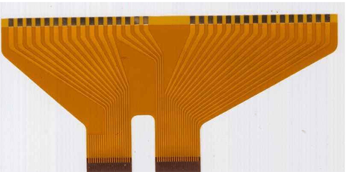
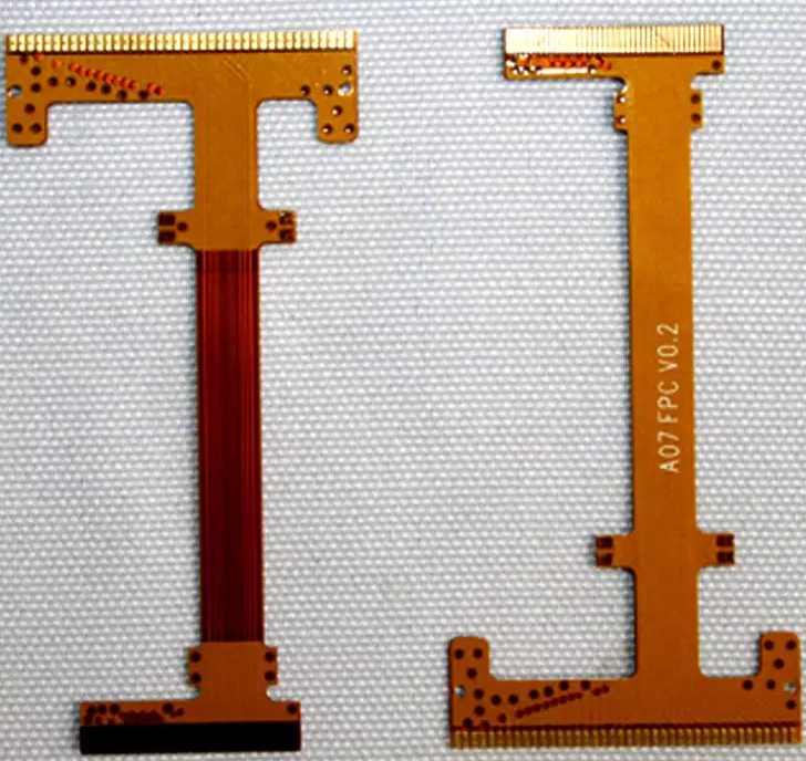
Flex circuits, also known as flexible printed circuits, are a type of electrical connection used in electronics. They consist of a thin, flexible substrate like polyimide film with conductive traces patterned on top. Flex circuits allow connections between electronic components that need to bend and flex repeatedly.
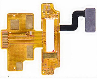
One component of some flex circuit designs is a stiffener. This is a thicker, more rigid layer attached to the flex circuit to provide mechanical support and strength. Stiffeners help prevent the thin flexible circuit from buckling and deforming under load. They also help dissipate heat and protect components.
In this article, we’ll look at how thick flex circuit stiffeners typically are. We’ll explore what factors determine the ideal stiffener thickness for an application. We’ll also discuss the tradeoffs involved in selecting a thinner versus thicker stiffener.
Typical Thicknesses

Flex circuit stiffeners are made from a range of materials including plastics like polyimide, polyester, PEEK, and metals such as stainless steel or beryllium copper alloys. The thickness depends on the application requirements but commonly ranges from around 0.10 mm to 2.5 mm.
Here are some typical thicknesses used:
- 0.10 – 0.13mm – Thin polyimide or polyester film stiffener
- 0.20 – 0.25mm – Thicker polymer stiffener for added rigidity
- 0.38 – 0.51mm – Metal stiffener for maximum support
- 1.0 – 2.5mm – Thick metal stiffener for high stiffness and heat dissipation
So in summary, a large range is possible but a good rule of thumb is:
- Polymer stiffeners: 0.1 – 0.3mm
- Metal stiffeners: 0.3 – 2.5mm
The required thickness depends on factors like:
Application/Use
What will the flex circuit assembly be used for? Is it a dynamic application involving frequent bending? Does it need to withstand vibration or shock loads? High stiffness and robustness requires a thicker stiffener.
Circuit Length
Longer circuits generally need a thicker stiffener for support. Short stiffeners may only need thin plastic film.
Number of Layers
More circuit layers or thicker copper increases thickness so the stiffener must match this.
Operating Temperature
Higher temperatures require thicker metal stiffeners for heat dissipation.
Stiffness Requirements
Some applications require very rigid, robust support. Other circuits are designed for high flexibility. The stiffener thickness is tailored to the needed stiffness.
Thin vs Thick Stiffeners
Deciding on the ideal stiffener thickness requires tradeoffs between competing needs:
Thin Stiffeners
Advantages:
- More flexible assembly
- Lower mass and thickness
- Easier to produce thin laminates
- Lower material costs
Disadvantages:
- Less rigid – can deform under load
- Poorer heat dissipation
- Less protection for components
- Prone to damage if bent excessively
Thick Stiffeners
Advantages:
- Maximum stiffness and component protection
- Excellent heat dissipation
- Prevents damage if flexed too far
- Can allow more layers and higher thickness circuits
Disadvantages:
- Increased mass and material usage
- Potentially difficult to laminate thick layers
- Reduced ability to flex and bend assembly
- Higher material cost
So in summary, thinner stiffeners prioritize flexibility and low weight, while thicker stiffeners focus on strength and robustness. The ideal choice depends on the specific demands of the application.
Stiffener Materials

There are various options when selecting a stiffener material:
Plastic Films
Polyimide, polyester (PET), and PEEK films are lightweight and easily laminated. Polyimide handles higher temperatures. The films can be metalized on one or both sides for electrical shielding.
Stainless Steel
Offers high strength and temperature resistance. Easy to stamp complex shapes. Can be given surface treatments to tailor electrical conductivity.
Beryllium Copper Alloys
An excellent match for flex circuits due to inherent spring properties. Allows repeated flexing without fatigue. Excellent electrical and thermal conductivity.
Aluminum Alloys
Lightweight and low cost option. Not as strong but dissipates heat efficiently. Easy to form and machine thin stiffeners.
Copper Alloys
Highly conductive so offers electromagnetic shielding. Strong and casts/machines well. Heavier than aluminum or steel alloys.
Titanium
Provides the best strength-to-weight ratio. Expensive but used when lightweight and robustness are critical.
Stiffener Fabrication
There are several ways to fabricate the stiffeners:
- Chemical etching – A photolithography process uses acid to etch the desired pattern into the metal foil. Allows intricate shapes.
- Die stamping – The material is stamped between a punch and die to cut out the shape. Best for higher volumes.
- CNC machining – A computerized machine like a mill or lathe cuts the stiffener geometry from stock material. For complex low volume parts.
- Water jet cutting – A high pressure jet of water slices through the material. No heat affected zone so good for sensitive alloys.
- Laser cutting – A high power laser cuts the outline profile. Provides precision with no tool contact.
- Photo-chemical machining – Similar to chemical etching but uses a laser to image the pattern. Good for delicate metals like beryllium copper.
The fabrication method depends on the capabilities of the flex circuit manufacturer. Photo-etching and die stamping are common high volume approaches.
Attaching the Stiffener
The stiffener layer must be precisely positioned and attached to the flex circuit. Here are some common bonding methods:
Adhesive laminating
The stiffener is aligned to the flex circuit then adhesive sheets, bonded with heat and pressure, attach the two permanently together.
Soldering
If the stiffener is a solderable metal like stainless steel, it can be reflow soldered to a flex circuit with metalized bonding pads. Gives a very strong bond.
Welding/brazing
Some metal stiffeners are welded or brazed to the flex circuit substrate. This creates robust high temperature bonds but requires compatible metals.
Mechanical fasteners
Screws, rivets or specialized clips can mechanically fasten the stiffener. Allows easy assembly/disassembly.
The surface finish and flatness are critical for good adhesive bonding. The stiffener must match the flex circuit’s coefficient of thermal expansion to prevent stress failures during thermal cycling.
Conclusion
In summary, stiffeners are an important component in many flexible circuit designs. Their thickness is selected based on the mechanical demands of the application and ranges from 0.1 – 2.5mm typically. Thicker stiffeners prioritize strength and heat dissipation while thinner ones favor flexibility. Many options exist for materials and fabrication methods. The stiffener is precisely aligned then bonded to the flex circuit substrate with adhesives, soldering, welding, or mechanical fasteners. With the right stiffener design, flex circuits can survive millions of dynamic bending cycles in demanding environments.
FQA
How do you determine the ideal stiffener thickness for a particular flex circuit application?
Some key factors to consider when selecting the stiffener thickness are:
- The length of the flex circuit – longer circuits need more support
- The number of conductive layers – more layers equals greater thickness
- The degree of bending required – highly dynamic flexing needs thinner stiffeners
- The expected vibration, shock, or loading forces
- The temperature range and power levels during operation
- The required electrical shielding and heat dissipation performance
- The weight restrictions and space constraints of the product
With these requirements in mind, engineers can model options using finite element analysis software to predict stresses and deformation. Prototypes with different thicknesses are often tested. This data drives the optimum stiffener design.
What are some ways to improve the reliability of stiffener adhesion?
To maximize the adhesive bond strength between the stiffener and flex circuit substrate:
- Ensure both surfaces are free of any contamination and moisture
- Prepare the surfaces, e.g. chemically etching to improve adhesion
- Apply adhesive evenly across the entire interface
- Use adhesives that are flexible when cured to allow for differences in CTE
- Cure the adhesive using the recommended heat and pressure levels
- Optimize the adhesive cure cycle time and temperature profile
- Perform regular quality checks of the cured bond strength
- Consider alternative bonding techniques like welding, brazing or soldering
Careful surface preparation, controlling the bonding process, and post-process testing helps create reliable stiffener adhesion.
How does the choice of stiffener material affect the flex circuit performance?
The stiffener material’s properties significantly impact the flex circuit:
Stiffness – This determines rigidity for supporting components. Harder materials like thick steel provide maximum stiffness.
Strength – Stronger materials like titanium alloys will not crack under repeated bending stress.
Flexibility – Materials like beryllium copper allow high elasticity and dynamic bending.
Thermal conduction – Metals like aluminum or copper help dissipate heat from circuits.
Electrical conduction – Conductors like beryllium copper provide electromagnetic shielding.
Weight – Dense metals add mass. Lighter polymers reduce weight.
Processability – The material affects manufacturability. Soft alloys like copper are easier to machine or etch.
Cost – Common metals like steel or aluminum minimize cost. Exotics like titanium are expensive.
Engineers balance all these factors when selecting an optimal stiffener material for the application.
Can multiple stiffeners be used on one flex circuit assembly?
Yes, large or complex flex circuits often use two or more separate stiffeners attached at different areas. Reasons include:
- Providing rigidity at multiple mounting or interface locations
- Managing different zones of mechanical stress across a large assembly
- Allowing regions with different degrees of flexibility
- Supporting heavier components in specific areas
- Integrating stiffeners made from different materials as needed
- Facilitating simpler stiffener fabrication and attachment
- Lowering costs by using less exotic materials only where essential
Careful structural analysis helps determine the ideal number and placement of stiffeners across a flex circuit assembly.
How are very thick metal stiffeners fabricated?
There are several methods for fabricating thick metal stiffeners over 2 mm thickness:
- Metal machining such as milling or turning can cut stiffeners from plate stock
- Metal forming techniques like stamping, pressing or forging can shape thick blanks
- Casting molten metal allows fabricating near-net shape stiffeners
- Welding thinner components creates thicker stiffeners
- Sintered metal powder can be pressed and fired into a solid stiffener
- Additive manufacturing via 3D printing builds up thick metal layers
The optimum process depends on the material, equipment capabilities, volume needs and complexity of the stiffener design. Secondary machining may still be required to achieve final dimensional accuracy.


Leave a Reply