Introduction
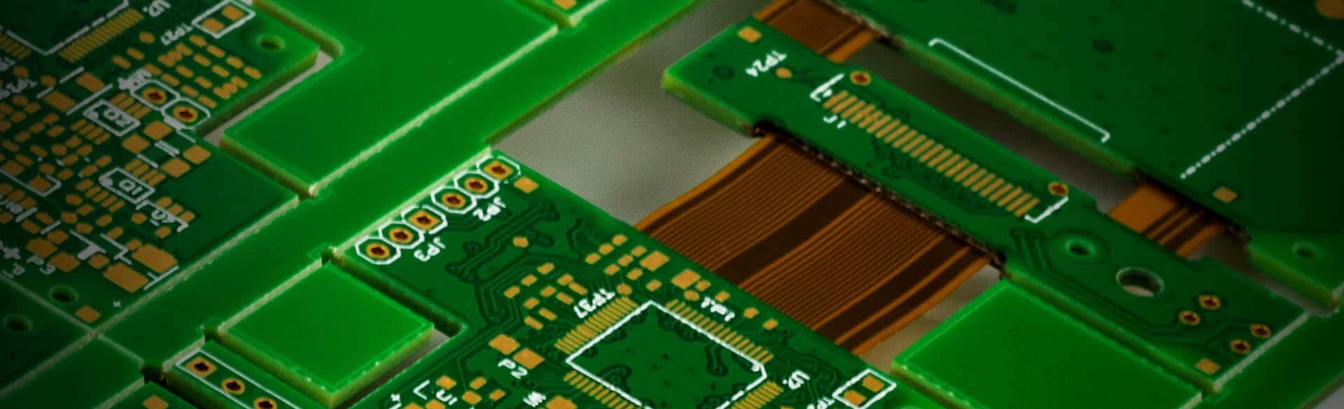
Printed circuit boards (PCBs) are essential components in nearly all modern electronics. They provide the foundation on which components are mounted and connected through conductive copper traces. An important aspect of PCB manufacturing is the plating of through holes, which allows traces on different layers of the board to be connected. But how thick is this plating? In this article, we’ll examine the typical thickness of PCB through hole plating, the factors that determine thickness, and why it’s an important consideration in PCB design and fabrication.
What is Through Hole Plating?
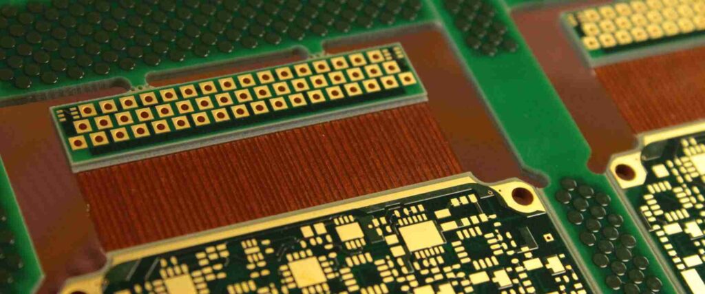
Through hole plating refers to the metal plating deposited on the interior walls of holes drilled through a PCB. These holes allow components leads to pass through and make connections between layers of the board.
The most common metal used for through hole plating is copper. The through holes are first drilled, then conditioned through chemical processes to properly prepare them for plating. Electroplating is then used to deposit copper onto the interior hole walls. The thickness of this plating determines the quality of the connection through the hole.
Typical Thickness of PCB Through Hole Plating
The thickness of plating for PCB through holes can range from 0.5 mils up to 2 mils (1 mil = 0.001 inches). However, the most common standard thickness used is 1 mil, or about 25 microns.
Here are some typical through hole plating thicknesses:
- 0.5 mils (12 microns) – Minimum for basic plated through holes
- 1 mil (25 microns) – Standard thickness for most applications
- 1.2 mils (30 microns) – For high-reliability boards
- 2 mils (50 microns) – Maximum thickness typically used
So in most cases, you can expect PCB through holes to have roughly 1 mil (25 microns) of copper plating thickness. This provides a good balance between conductivity, cost, and manufacturability.
Factors that Determine Through Hole Plating Thickness
There are several factors that help determine the appropriate through hole plating thickness for a particular PCB design:
- Current carrying capacity – Thicker plating can handle higher amperage. Important for power circuit boards.
- Number of holes – More holes require thicker plating to avoid over-deposition.
- Reliability requirements – Thicker plating improves hole lifespan. Important for high-reliability boards.
- Plating process – Equipment used affects uniformity of plating thickness.
- Via size – Smaller holes may need thinner plating.
- Cost – Thicker plating increases manufacturing cost.
The PCB fabricator will take all of these factors into account when determining the plating thickness for a board design.
Importance of Proper Through Hole Plating Thickness
Having the proper thickness of plating in PCB through holes is important for several reasons:
- Electrical conductivity – The plating allows electric current to flow between layers of the board. Thin plating can increase resistance.
- Component lifespan – Thicker plating allows leads to be inserted and removed more times without wearing down the hole. This improves component replaceability.
- Manufacturability – Adequate plating thickness prevents holes from cracking or being blocked during fabrication. It also allows for uniform electroplating.
- Solderability – Sufficient plating provides a proper surface for solder to adhere to in through holes. This ensures reliable solder joints.
- Corrosion resistance – The copper plating helps prevent hole walls from oxidizing and corroding over time, maintaining conductivity.
So in summary, proper through hole plating thickness ensures the long-term functionality of PCB holes, allowing them to reliably interconnect components on the board.
Through Hole Plating Thickness Guidelines
To recap, here are some general guidelines for typical PCB through hole plating thicknesses:
- Minimum functional thickness is 0.5 mils (12 microns)
- Standard thickness for most boards is 1 mil (25 microns)
- High-reliability boards use 1.2 mils (30 microns) or more
- Maximum useful thickness around 2 mils (50 microns)
Keep in mind that different PCB fabricators may have specific capabilities and recommendations for plating thickness as well. Consulting with them is important to determine the optimal thickness for your particular design needs and manufacturing process.
Through Hole Plating Thickness Table
Here is a table summarizing typical through hole plating thicknesses for different applications:
| Application | Plating Thickness |
|---|---|
| Minimum functional | 0.5 mils (12 μm) |
| Standard reliability | 1 mil (25 μm) |
| Medium/high reliability | 1.2 mils (30 μm) |
| Maximum useful | 2 mils (50 μm) |
Through Hole Plating Thickness Measurement
Since proper plating thickness is important, methods are needed to measure it. Here are some ways through hole plating thickness can be measured:
- Cross-sectioning – Cutting a cross section of the board and examining it under a microscope. Provides accurate local measurement.
- Microsectioning – Taking a small micro-sample of the hole wall and measuring thickness. Preserves board.
- Laser micrometer – Shining a laser perpendicular to the hole wall and measuring reflection. Non-destructive.
- Eddy current – Using induced electrical currents in the plating to measure thickness. Requires access to both sides of hole.
- Coulometric reduction – Measuring electrical charge needed to dissolve the plating. Provides precise average thickness.
- Vision system – High-resolution imaging and software analysis to measure thickness. Fast, non-contact.
Whichever method is used, taking measurements in multiple locations across a board is important to verify uniform plating thickness and ensure manufacturing quality.
Factors that Can Affect Through Hole Plating Thickness
There are a several variables that can influence the plating thickness achieved for PCB through holes:
Board Design Factors
- Number, size, and density of holes
- Complexity of board layout and routing
- Stackup and aspect ratio of holes
Process Factors
- Plating equipment capability and settings
- Preparation chemicals and hole conditioning
- Plating bath composition and temperature
- Agitation and circulation of plating solution
Quality Control Factors
- Measurement and monitoring of plating thickness
- Maintenance of plating baths and equipment
- Operator training and process documentation
Careful control of these factors helps maximize plating uniformity and achieve the desired thickness across all through holes on a board.
Conclusion
In summary, typical PCB through hole plating thicknesses fall between 0.5-2 mils, with 1 mil being standard for most applications. Proper plating thickness ensures good conductivity and manufacturability while avoiding increased costs from over-plating. Thickness depends on current needs, reliability, hole size, and fabrication process. Measuring plating thickness in multiple locations validates quality and uniformity. Keeping plating variables under control maximizes the consistency of plating results across a PCB.
Frequently Asked Questions
What is the minimum usable through hole plating thickness?
The minimum functional thickness for basic plated through holes is around 0.5 mils (12 microns). Thinner plating risks reliability issues and increased resistance.
How thick can you plate a PCB through hole?
Through holes can theoretically be plated up to around 2-3 mils (50-75 microns) thickness, but more than 2 mils is not typically useful. Excessively thick plating provides little added benefit and just increases PCB fabrication costs.
Does thicker plating increase hole lifespan?
Yes, thicker plating allows component leads to be inserted and removed more times without wearing down the copper plating in the hole. This makes components more replaceable over the lifetime of the board.
Can you use too thick of plating?
Overly thick plating over 2 mils provides minimal added advantages and can actually cause problems like increased hole wall stress or challenges soldering leads. It also raises PCB fabrication costs unnecessarily. Around 1-1.5 mils is ideal for most boards.
How do you measure plating thickness inside a hole?
Common ways to measure through hole plating thickness include cross-sectioning, microsectioning, laser micrometers, eddy current techniques, coulometric reduction, and high-resolution vision systems. Taking measurements at multiple locations ensures accuracy.


Leave a Reply