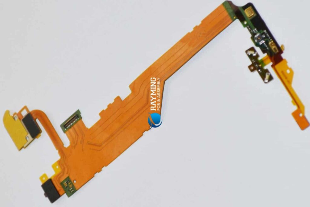
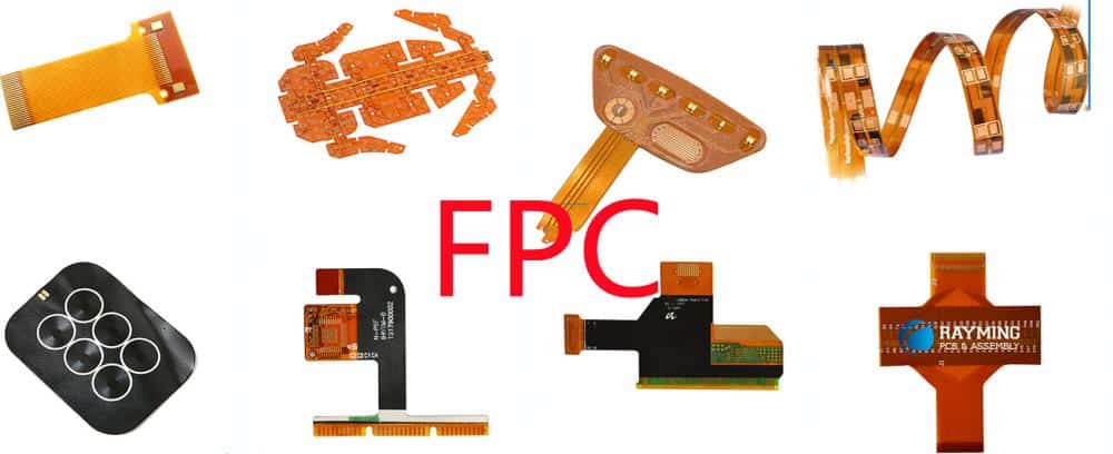
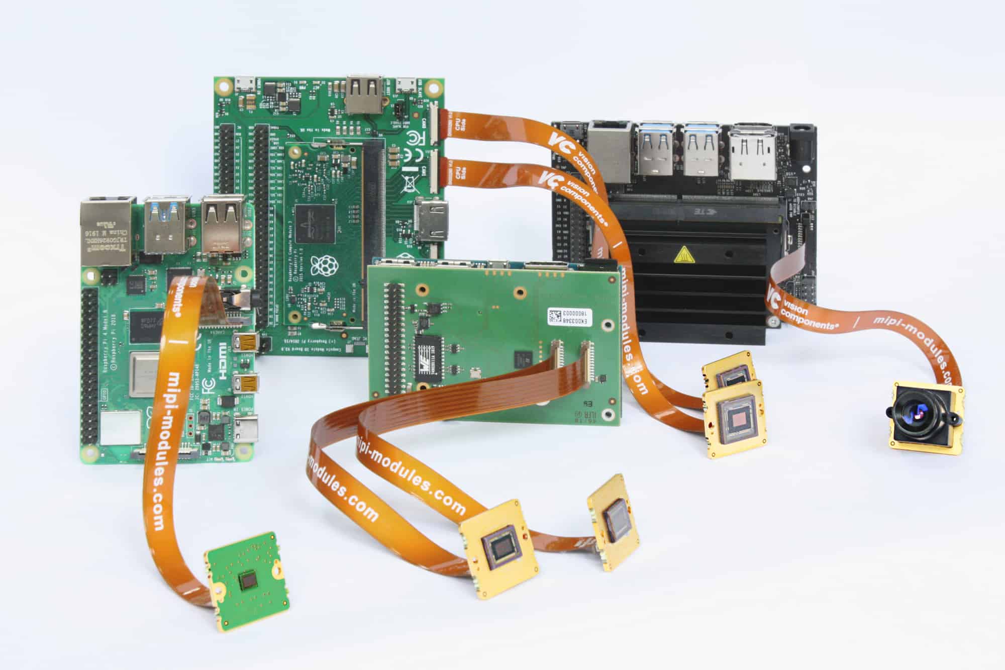
A PCB (printed circuit board) stiffener is a plate that is attached to the PCB to strengthen and support the board. The thickness of the stiffener will depend on a variety of factors, including the size of the PCB, the number of components mounted on the board, and the amount of flexing or vibration the board will undergo during use. This article will examine the typical thickness range for PCB stiffeners and the considerations that go into selecting the right thickness.
Typical Thickness Range

Most PCB stiffeners range in thickness from 0.8mm to 6mm. Here are some general guidelines on stiffener thickness:
- 0.8mm – 1.2mm – This is the minimum thickness used for basic support on small PCBs. Stiffeners this thin are made from aluminum or steel.
- 1.5mm – 2.5mm – A mid-range thickness good for medium sized PCBs. This can provide adequate strength while minimizing weight.
- 3mm – 6mm – Thicker stiffeners for large PCBs, heavy components, or boards subject to frequent vibration/flexing. Maximum strength and rigidity.
Factors That Determine Stiffener Thickness
There are several key factors that help determine the ideal thickness for a particular PCB stiffener:
PCB Size
- Larger PCBs will require a thicker stiffener to prevent warping or bowing
- Small PCBs can get by with a thinner 0.8-1.2mm stiffener
- For PCBs up to 75 x 75 mm, 1.5mm is usually sufficient
- Full-size ATX motherboards may need 4mm+ stiffeners
Component Density
- PCBs with many large, heavy components (e.g. capacitors, transformers) exert more stress and require thicker stiffeners
- Boards with lightweight surface mount components can use thinner stiffeners
- Cards with large heatsinks or other protruding components should have appropriately thick stiffeners to avoid flexing
Vibration/Shock Exposure
- PCBs in devices subject to frequent vibration or shock loads require thicker stiffeners for strength
- Examples include automotive, aerospace, handheld electronics
- Stationary boards can use thinner stiffeners
Stiffener Material
- Aluminum stiffeners can be made thinner than steel for equal strength
- Plastics like FR4 require greater thickness to match metal stiffness
- Metal matrix composites are stiff yet lightweight
PCB Layer Count
- Boards with more layers exert more force when flexing
- High layer count boards (>8 layers) should use thicker stiffeners
Cost Constraints
- Thicker metal stiffeners add cost in material and machining
- Thinner stiffeners reduce costs but sacrifice some strength
So in summary, a 0.8mm aluminum stiffener would be suitable for a small, lightweight PCB with minimal flexing, while a 6mm steel stiffener would be used for maximum strength on a heavily loaded large board in a high vibration environment. Selecting the right thickness involves balancing the factors of board size, component density, vibration, material, layer count, and cost.
Stiffener Thickness Selection Process
Here is a step-by-step process for determining the optimal stiffener thickness for a new PCB design:
- Evaluate PCB size – The length and width of the board will indicate if a thinner or thicker stiffener is needed. Larger boards need more support.
- Review component layout – Are there heavy components or connectors that will exert significant forces on the board? These will require a stiffer stiffener.
- Assess vibration/shock loads – Consider the operating environment and any repetitive forces acting on the board that could cause flexing. These conditions demand thicker stiffeners.
- Determine stiffener material – Check if the design calls for aluminum or steel stiffeners, which have different stiffness properties.
- Consider PCB layer count – More layers means more potential for warpage and need for thickness. High speed designs with tightly controlled impedances may need thicker stiffeners.
- Check cost constraints – Thicker stiffeners add cost. Determine if the budget allows for thicker material or if a thinner compromise is necessary.
- Review stackup height – The distance between the PCB and any mounted components cannot be less than the stiffener thickness.
- Select stiffener thickness – With all factors considered, choose the minimum thickness that provides adequate strength for the particular application.
- Perform modeling/testing – Use FEA tools to model board stresses and optimize the design. Vibration testing can validate the real-world effectiveness of the chosen thickness.
- Implement stiffener in design – Incorporate the stiffener in the PCB CAD layout in the appropriate location to maximize support.
Following this process will help arrive at an ideal stiffener thickness that provides sufficient strength and rigidity without overdesigning or inflating costs. The thickness is determined on a case-by-case basis for each PCB design and its requirements.
PCB Stiffener Design Guidelines

Here are some key guidelines to follow when designing and implementing PCB stiffeners:
- Position the stiffener close to the center of the PCB for maximum stabilization.
- Align the stiffener parallel to the longest dimension of the board.
- Use multiple stiffeners on very large boards to provide support at intervals.
- Extend the stiffener to match the full length or width of the PCB when possible.
- Allow small clearance gaps of 0.1-0.2mm between stiffener and components to avoid shorts.
- Avoid placing components in areas where the stiffener will be located.
- Use chamfers or rounded corners on the stiffener edges to reduce stress concentrations.
- If necessary, use notches or cutouts in the stiffener to clear large components.
- Solder or use adhesive to firmly attach the stiffener to the PCB surface.
- Verify that the stiffener thickness keeps components within their specified stackup height limits.
Properly designing stiffener dimensions, location, and attachments ensures maximum benefit in strengthening the PCB.
PCB Stiffener Materials
PCB stiffeners can be fabricated from different materials including metals and plastics. Here are some of the common options:
Aluminum – Most widely used material due to its high stiffness and low cost. 6061 and 7075 alloys offer good machinability. Can be anodized for insulation. Thinner than steel for equal strength.
Stainless Steel – More expensive than aluminum but offers higher strength and temperature resistance. 304 and 17-4PH grades are commonly used. Low thermal expansion.
Cold Rolled Steel – Low cost material with high rigidity suited for cost-driven designs. Not as corrosion resistant as stainless steel. Typically zinc plated.
FR4 – Glass-reinforced epoxy laminate also used in making PCB substrate. Low cost but requires greater thickness than metals.
Beryllium Copper – Expensive but has very high elastic modulus for excellent stiffness. Used for high vibration environments.
Titanium – Excellent strength-to-weight ratio but costly. Used for weight critical applications like aerospace.
Plastics – Engineering plastics like PEEK, polycarbonate, ABS provide good economy but less rigidity than metals.
The choice of stiffener material depends on factors such as cost, strength needs, corrosion resistance, thermal properties, and weight constraints.
Finite Element Analysis of PCB Stiffeners
Finite Element Analysis (FEA) is a computer simulation technique that can be used to model and analyze the structural behavior of PCB stiffeners. Some benefits of using FEA for stiffener design:
- Predicts deflection, stress, and strain on the PCB with and without stiffener.
- Validates and optimizes stiffener thickness for the particular design.
- Evaluates impact of different stiffener materials and placements.
- Shows potential failure points and fatigue life.
- Reduces need for physical prototyping and testing.
The general FEA workflow involves:
- Creating CAD model of PCB and stiffener geometry
- Meshing model into finite elements
- Adding material properties (e.g. modulus of elasticity, Poisson’s ratio)
- Applying boundary conditions (constraints, loads)
- Running solver to analyze model
- Reviewing results for displacements, stresses, reactions
- Iterating with design changes to optimize stiffener performance
Common FEA software tools like ANSYS, ABAQUS, and SolidWorks Simulation are used for PCB stiffener modeling. With powerful computing capabilities, FEA provides valuable insights into stiffener effectiveness long before physical prototypes are built.
Testing PCB Stiffeners
In additional to simulation, physical testing is important to validate the real-world performance of PCB stiffeners. Some example testing methods include:
Vibration Testing – Applies harmonic vibration loads across a range of frequencies to identify resonant frequencies and induce failures. Used to qualify stiffeners for vibration environments like automotive, aircraft, etc.
Shock/Drop Testing – Subjects PCBs to high G-forces through mechanical shocks and free-fall drops. Checks for component detachment, cracks, and malfunctions.
Fatigue Testing – Cycles stiffened PCBs through repetitive loads like bend tests to determine long term durability and mean cycles to failure.
Thermal Cycling – Alternates PCBs between temperature extremes to induce thermal stresses and find potential points of failure.
Visual Inspection – Cross-sectioning and microscopy to check for proper stiffener attachment, voiding, delamination, and other defects.
Testing validates stiffener integrity, robustness, and workmanship while exposing points of weakness in the design or manufacturing process. Results help improve thicknesses, materials, attachment methods, and other factors.
PCB Stiffener Suppliers
There are a number of metal fabrication shops and PCB hardware suppliers that manufacture custom PCB stiffeners:
- Metal Etching Services – Offer stiffeners etched from aluminum and steel sheets for rapid prototypes and low volumes
- Bylaws Engineering – Specializes in Beryllium copper stiffeners with high rigidity
- Precision Metal Works – Supplies custom machined aluminum stiffeners up to 36″ x 48″ sizes
- Miraco Inc. – Manufactures powder coated cold rolled steel stiffeners
- Swift Textron – Provides titanium and Invar alloy stiffeners for aerospace applications
- Plascore – Supplies stiffeners made from honeycomb composite panels
- Sunshine Metals – Has catalog of standard FR4 and G10 stiffener sizes and custom fabrication
- Anaren – Designs microwave PCB rigidizer frames including CAD models for RF boards
For critical applications, working with a proven stiffener supplier that can provide design assistance and modeling support is recommended.
Stiffener Design Tips
Here are some helpful design tips when developing your PCB stiffener:
- Focus stiffener around perimeter rather than center for easier assembly access.
- Use ribbed stiffeners or honeycomb structures for high strength at lower weights.
- Incorporate thermal vias under stiffener in 4-layer boards to aid heat dissipation.
- Limit stiffener overhang to under 2 mm to avoid snagging during handling.
- Place notches in stiffener underneath large bypass capacitors to allow for flux cleaning during soldering.
- Specify generous internal rounded corners and edge chamfers to reduce stress concentrations.
- If coating stiffener, choose conductive coating for grounding or insulating coating for electrical isolation.
- For extra support, use stiffeners on both sides or sandwich PCB between two stiffener plates.
- Ensure flatness, thickness consistency, and precise dimensions to support tight component clearances.
Proper stiffener design avoids many issues encountered in manufacturing assembly, test, and operation of the PCB in its intended application.
Frequently Asked Questions
Here are answers to some common questions about PCB stiffener thickness:
How is stiffener thickness tolerance normally specified?
For metal stiffeners, a tolerance of +/- 0.10 mm is typically used. Tighter tolerances can be achieved but cost more. FR4 stiffeners are usually +/- 0.15 mm.
What is the maximum thickness for a BGA stiffener?
BGA package height limits the stiffener thickness. Typical maximum is around 2.5 mm for standard BGAs. For larger BGA arrays, 3-4 mm thick stiffeners may be possible.
Can multiple thin stiffeners be used instead of one thick stiffener?
Yes, using two 1 mm stiffeners bonded together may be cheaper than one 2mm piece for metals like aluminum or titanium. Performance is likely still adequate.
How do I determine if my PCB really needs stiffeners?
Factors like large board size, high layer count designs, dense components, large protruding heatsinks, and vibration environments typically indicate when stiffeners are required for preventing warpage.
What design tools can I use for modeling stiffener performance?
FEA software like ANSYS and SolidWorks Simulation are great tools for optimizing stiffener thickness and location through stress analysis. Thermal modeling tools can also help with thermal warpage effects.
Conclusion
PCB stiffeners are important reinforcements that prevent board warpage and provide structural integrity. Careful consideration must be given to selecting the optimal stiffener thickness, which typically ranges from 0.8mm to 6mm depending on size, components, materials, vibration, and other factors. Simulating and testing stiffener designs ensures adequate strength is achieved without over-engineering. Following proven design guidelines for placement and geometry will result in a cost-effective stiffener solution tailored for the particular requirements of each printed circuit board.


Leave a Reply