Introduction to PCB cores
Printed circuit boards (PCBs) are the foundation of modern electronics. They provide the mechanical structure and electrical connections for components like integrated circuits, resistors, capacitors, and more. At the heart of every PCB is the core – also known as the substrate. This core material provides insulation between copper traces and determines fundamental properties like flexibility and dielectric constant.
As electronic devices become more compact and complex, there is an increasing demand for thinner and smaller PCB cores. A thinner core allows routing of finer traces and vias, enabling higher component density and more circuit layers. It also reduces overall thickness, a critical parameter for space-constrained mobile and wearable devices. But determining the absolute thinnest possible PCB core requires balancing electrical, mechanical, and manufacturing considerations.
Types of cores
There are several common types of PCB cores:
- FR-4 – The most popular core by far. Made of woven fiberglass cloth with an epoxy resin binder. Offers good mechanical strength and dielectric properties. Standard thickness is 1.6mm.
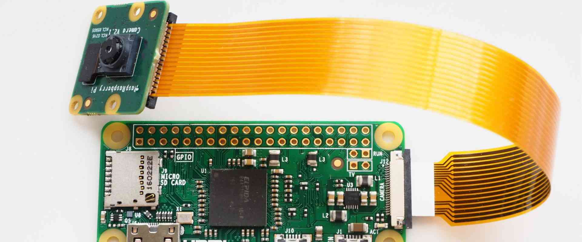
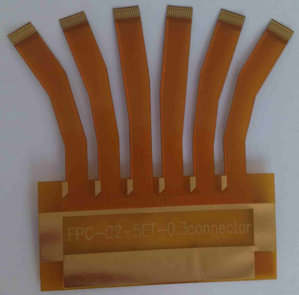
- Flexible PCB – Uses polyimide instead of FR-4 for the base material. Extremely thin cores down to 25μm are possible to enable flexible circuits.
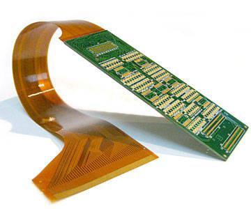
- Rigid-flex – Combines rigid FR-4 sections with flexible polyimide. Allows complex 3D structures.
- Metal core – Uses an aluminum baseplate for thermal dissipation, with dielectric layers on top.
- Ceramic – High performance but expensive option using ceramic materials. Used for specialized applications.
Thickness considerations
The thinnest viable core thickness depends on several factors:
Mechanical strength – Thinner cores are naturally more fragile. They are susceptible to warping and fractures without proper handling in manufacturing and assembly.
Manufacturing capabilities – Thinner materials are harder to process with standard PCB fabrication techniques. And they may require more expensive manufacturing tools.
Component density – Thinner dielectrics allow tighter trace spacing and routing for high density designs. But below a certain point the core thickness is insufficient for reliable isolation.
Layer count – Stacking more copper layers allows more complex routing. But each layer adds thickness. Ultra-thin cores may limit layer counts.
Thermal dissipation – Thinner cores provide less thermal mass for heat spreading. This could lead to hotter components. Metal cores help alleviate this.
Dielectric properties – Materials thinner than a certain threshold no longer maintain their nominal dielectric breakdown voltage and insulation resistance.
There are always tradeoffs between these factors when selecting an optimal PCB core thickness for a particular application.
Review of Thinness Limits
Let’s examine the practical limitations of ultra-thin PCB cores based on current materials and manufacturing capabilities:
Flexible cores
Flexible cores use polyimide foil as the dielectric material. This enables extremely thin and bendable PCBs.
Polyimide flexible cores
- Polyimide thickness range: 12.5μm – 150μm
- Minimum bend radius: 0.1mm (at 25μm)
- Layer count: Typically single or double sided
- Example applications: Wearables, medical sensors, flexible displays
The thinnest polyimide cores commercially available are around 12.5μm. But there are R&D efforts pushing below 10μm. Extremely thin cores below 20μm become highly fragile and require special handling. They also have reduced insulation properties. So thicker polyimide foils in the 25-50μm range are more widely used.
Rigid FR-4 cores
Rigid FR-4 remains the workhorse PCB substrate for its balance of cost and performance.
FR-4 rigid cores
- Standard thickness range: 0.4mm – 1.6mm
- Minimum thickness: ~0.1mm
- Layer count: Up to 30+ layers possible
- Example applications: Consumer electronics, IoT devices, automotive, aerospace
While standard FR-4 cores for common PCBs are 0.4-1.6mm, high density designs can use thinner 0.2-0.3mm cores for tight trace routing. On the extreme end, R&D efforts have produced 0.07-0.1mm cores. But these have limited mechanical strength and are challenging to manufacture. 0.2mm is typically considered the practical limit for FR-4 rigid cores.
Case Study: 0.07mm Rigid Flex PCB
Let’s examine a case study of an extremely thin 0.07mm PCB fabricated using rigid-flex technology.
In 2018, researchers at Georgia Tech published work on developing ultra-thin rigid-flex PCBs for electronic skins and biointegrated applications [1]. They used liquid crystal polymer (LCP) and polyimide to produce rigid sections down to 70μm thick, connected by 25μm thick polyimide flexible layers.
To enable such thin rigid sections on the PCB, the team had to use a modified manufacturing process:
- Spin coating instead of laminating for dielectric layers
- Thin nickel plating instead of standard copper for traces
- Precision laser ablation instead of mechanical drilling for vias
- E-beam deposition for solder mask rather than traditional liquid coatings
This demonstrates the kinds of specialized processes that become necessary for fabricating PCBs below 0.1mm. The thin nickel traces are limited to modest current densities compared to standard copper. And overall board durability is reduced. So applications are restricted to low power electronics.
The researchers presented the ultra-thin PCBs as enabling electronic systems to be embedded into thin substrates like paper and synthetic skin. The biointegrated circuits could potentially support applications in robotics, prosthetics, and health monitoring devices.
While still an area of ongoing research, the project highlights the possibilities at the leading edge of PCB core thickness.
Outlook on Future Core Thickness Limits
What does the future hold for ultra-thin PCB cores? Here are some insights on approaching the fundamental limits:
Materials development – Creating polymer dielectric materials optimized for ultra-thin cores could improve electrical and mechanical properties. Ceramic and glass fabrics are also being explored.
Novel processing – Additive manufacturing like inkjet and aerosol printing may enable dielectric deposition and trace printing at smaller scales than traditional methods.
2.5D integration – Stacking and connecting multiple ultra-thin cores with high density interconnects can achieve similar densities as an ultra-thin single core.
Alternative conductors – Conductive nano-materials like graphene and carbon nanotubes could replace copper at nanometer scales.
Active devices integration – Monolithic integration of active components like transistors into the core during fabrication could reduce the need for ultra-fine traces.
With these innovations, cores less than 10μm thick may become feasible. But they will remain highly specialized and expensive. For most applications, 25-100μm is likely to remain the practical limit for the foreseeable future. Striking the right balance of thickness, performance, and cost for a given application will continue to be key. But PCB core technology will keep enabling ever more compact and integrated electronic systems.
FAQ
What is the main purpose of a PCB core?
The core provides mechanical support and electrical insulation between the conductive copper traces of a printed circuit board. It acts as the foundational substrate on which the traces and other layers are built.
Can flex PCBs be used in rigid PCB applications?
In some cases, yes. Flex PCBs using polyimide cores can potentially replace rigid FR-4 PCBs when the superior flexibility is not required. The thinner and lighter polyimide can save weight and space. But material costs are higher, and electrical performance is reduced compared to FR-4.
Are there disadvantages to using a thinner PCB core?
Thinner cores tend to be more fragile and susceptible to damage. They also have lower insulation resistance and breakdown voltage. This can limit component density and trace proximity. And thinner dielectric results in increased crosstalk noise between signals.
How does core thickness affect PCB layer count?
Thinner cores allow more circuit layers to be stacked for a given overall PCB thickness. This helps increase routing density. But extremely thin cores may not have the dimensional stability and robustness for high layer counts.
Can PCB cores be made of ceramic or glass?
Yes, ceramic and glass cores are an expensive specialized option used in very high frequency and performance applications. The superior dielectric properties provide excellent insulation even at microwave frequencies, with the tradeoff of fragility.


Leave a Reply