Flexible printed circuit boards, also known as flex circuits or flex boards, are thin flexible circuits that can be bent and folded to fit into tight spaces. They provide electrical connections between components while still allowing mechanical motion and flexibility. Flex boards are used in a wide variety of applications where rigid printed circuit boards (PCBs) are impractical.
Applications of Flex Boards
Consumer Electronics
Flex circuits are commonly found inside consumer electronics like mobile phones, laptops, tablets, cameras, and wearables. They connect small components like batteries, screens, sensors, buttons, and cameras while folding into the tight space constraints of these devices. Specific uses include:
- Connecting phone or tablet components like the battery, display, logic board, buttons, and cameras. Flexible connections allow folding and bending.
- Wearable tech like smart watches and fitness trackers. Flex boards connect components and wrap around wrists.
- Cameras and digital video equipment. Flexible connections needed for lenses, sensors, and folding screens.
Medical Devices
In medical devices like hearing aids and pacemakers, flex circuits provide connections while conforming to irregular shapes. Common applications include:
- Hearing aids. Flex circuits fold into the contours of behind-ear and in-ear hearing aids.
- Pacemakers and other implantable devices. Flexible circuits can safely conform inside the human body.
- Imaging equipment like endoscopes. Flex boards connect components along bended tubes.
Automotive
Vehicles utilize flex boards to connect components and provide signals across moving parts like gears, pedals, doors, mirrors, and seats. Example automotive uses are:
- Connecting electronics in gear shifters, pedals, steering wheels, and control panels.
- Wiring for movable mirrors, seats, doors, and convertible roofs.
- Sensors mounted in tight spaces like tire pressure monitoring systems.
Industrial
In industrial equipment, flex circuits can provide connections that withstand vibration, movement, and contamination. Applications include:
- Connecting sensors and controls in factory automation systems, robots, and motion control systems.
- Aerospace and aviation equipment with moving control surfaces.
- Connecting sensors and transmitters in smart energy meters and grids.
Military and Defense
The military employs flex boards in guidance systems, weapons, vehicles, aircraft, and body-worn tech to withstand G-forces and demanding conditions.
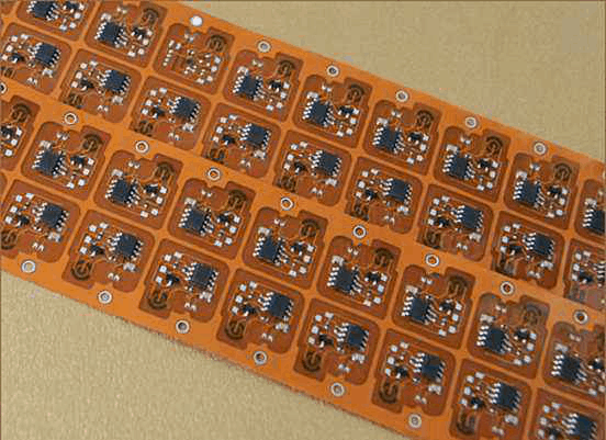
Construction and Composition
Flex boards consist of conductive copper traces laminated onto a thin flexible insulating substrate material. This allows the circuit to bend and flex without breaking the conductive pathways.
Layers
The simplest flex boards contain a single layer of copper conductors on a flexible polymer substrate. However, many flex circuits consist of multiple conductive layers separated by adhesive dielectric layers. Multilayer boards accommodate more complex interconnections in limited space.
Typical layer counts are:
- Single layer: one conductive layer
- Double layer: two conductive layers
- Multilayer: three or more conductive layers
Common Substrate Materials
The flexible insulating material which forms the substrate for the conductive layers include:
- Polyimide: This is the most common flexible circuit substrate. Polyimide (Kapton) provides excellent thermal durability and chemical resistance.
- Polyester: Polyester films like PET provide an economical substrate option. They have relatively lower maximum temperatures than polyimide.
- Polyethylene: Flexible low-density polyethylene has very low water absorption. It provides excellent electrical insulation.
- Fluoropolymers: PTFE fiberglass-reinforced substrates offer robust thermal, chemical, and flame resistance.
Conductors
The conducting layers are typically made from electrodeposited copper foil. However, alternative conductors like aluminum or conductive ink can also be used for specialized applications.
Bonding Materials
The conductive layers are bonded to the substrate using adhesive materials like acrylic, epoxy, phenolic butyral, or polyimide. These adhesives provide high strength and flexibility.
Advantages of Flex Circuits
Compared to rigid printed circuit boards, flexible PCBs provide:
- Smaller Size: Flex boards fold into tight spaces and integrate multiple layers for complex circuitry.
- Lighter Weight: Thin, lightweight construction reduces mass.
- Flexibility: Bends and folds to fit odd geometries and allow motion.
- Reliability: Dynamic flexing withstands millions of cycles without failure.
- Simpler Assembly: Components mount directly onto flex board.
- Thinner Connections: Flexible interconnects fit into thinner assemblies.
Design Considerations
Designing reliable flex boards requires paying careful attention to:
- Bend radius: Avoid sharp folds which concentrate stress.
- Conductor spacing: Keep lines spaced adequately apart for flexibility.
- Strain relief: Use techniques like zig-zag or serpentine conductors in dynamic areas.
- Layer stacking: Ensure laminate materials and adhesives are compatible.
- Component attachments: Use methods like cutouts, slots, or surface mounts.
Manufacturing Process
Producing flex boards involves specialized fabrication techniques, including:
Imaging
A photolithographic process transfers the circuit layout onto the conductive layers using an etching resistant coating and selective light exposure.
Etching
Chemical etching removes excess copper not protected by the resist coating, leaving only the desired conductor pattern.
Lamination
Individual flex board layers are bonded using adhesives at high heat and pressure to fuse together conductors, substrates, and vias.
Drilling
Holes are drilled for mounting components and creating conductive vias between layers.
Plating
Plated through holes and vias provide conductivity between layers.
Testing and Inspection
100% electrical testing and automated optical inspection ensure quality standards.
Flex Board vs Rigid Flex
Rigid-flex PCBs combine rigid FR-4 fiberglass substrate sections with flexible polyimide sections to provide dense connections, save space, and allow movement in one structure. They contain:
- Rigid portions with components requiring sturdiness.
- Flexible portions for dynamic folding areas.
- Plated edge connections between rigid and flex sections.
Rigid-flex combines the benefits of both rigid and flexible PCBs. The rigid sections provide stability while the flexible sections allow motion. Products like mobile phones and military systems often utilize rigid-flex designs.
FQA
What are the key benefits of using a flex circuit?
The main benefits of flex circuits compared to rigid PCBs are:
- Smaller size – can fold into tight spaces
- Lighter weight from thin construction
- Dynamic flexibility – withstand repeated bending
- Simpler assembly – components mount directly on flex board
- Reliability – tested for millions of flex cycles
- Thin, space saving connections
What materials are used to make flex circuits?
The main materials are:
- Substrate – Polyimide is most common. Also polyester, polyethylene.
- Conductors – Copper foil, sometimes aluminum or conductive ink.
- Bonding – Acrylic, epoxy, phenolic butyral or polyimide adhesives.
What are some examples of products that use flex boards?
Typical applications include:
- Consumer electronics – phones, laptops, wearables
- Medical – hearing aids, pacemakers
- Automotive – mirrors, sensors, control panels
- Industrial – automation systems, robotics
- Military – guidance systems, bodywear
How do rigid-flex boards differ from flex boards?
Rigid-flex PCBs combine:
- Rigid fiberglass sections for component stability
- Flexible polyimide sections for dynamic folding
- Plated edges to connect rigid and flex sections
They provide both stability and flexibility in one board.
What design factors need special consideration for flex boards?
Key flex board design considerations:
- Bend radius – avoid sharp folds
- Conductor spacing – ensure adequate gaps
- Strain relief – use zig-zag or serpentine traces
- Layer compatibility – ensure laminate adhesion
- Component attachments – allow for flexibility


Leave a Reply