What is a Flyback Converter?
A flyback converter is a type of isolated switching power supply that utilizes a transformer to store energy and deliver it to the output load. It is widely used in low to medium power applications, such as battery chargers, LED drivers, and power adapters for electronic devices. The flyback converter is known for its simplicity, cost-effectiveness, and ability to provide isolation between the input and output stages.
Basic Principles of Operation
The flyback converter operates on the principle of energy storage and release through a transformer. The transformer consists of a primary winding connected to the input power source and a secondary winding connected to the output load. The primary and secondary windings are coupled through a magnetic core, allowing energy transfer between them.
The flyback converter works in two distinct phases:
-
Energy Storage Phase: During this phase, the switch (usually a MOSFET) connected to the primary winding is turned on. Current flows through the primary winding, storing energy in the transformer’s magnetic core. The diode on the secondary side is reverse-biased, preventing current flow to the output.
-
Energy Release Phase: When the switch is turned off, the energy stored in the transformer’s magnetic core is released. The polarity of the voltage across the secondary winding reverses, forward-biasing the diode. Current flows through the secondary winding, delivering energy to the output capacitor and load.
The flyback converter regulates the output voltage by controlling the duty cycle of the switch, which determines the amount of energy stored and released in each switching cycle.
Flyback Transformer
The flyback transformer is a critical component in the flyback converter. It serves multiple purposes:
-
Energy Storage: The transformer’s magnetic core stores energy during the energy storage phase.
-
Voltage Conversion: The turns ratio between the primary and secondary windings determines the voltage conversion ratio between the input and output.
-
Isolation: The transformer provides galvanic isolation between the input and output stages, ensuring safety and preventing ground loops.
The flyback transformer is designed with an air gap in the magnetic core to prevent saturation and allow for energy storage. The air gap also helps to reduce the transformer’s magnetizing inductance, enabling faster energy transfer and improved efficiency.
Advantages of Flyback Converters
Flyback converters offer several advantages that make them a popular choice for various power conversion applications:
-
Simplicity: Flyback converters have a relatively simple topology compared to other isolated switching power supplies. They require fewer components, reducing the overall cost and complexity of the design.
-
Wide Input Voltage Range: Flyback converters can operate over a wide range of input voltages, making them suitable for applications with varying input power sources.
-
Isolation: The flyback transformer provides galvanic isolation between the input and output stages, enhancing safety and preventing ground loops.
-
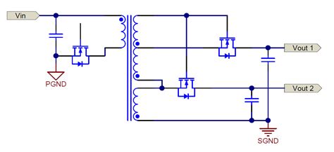
Multiple Outputs: Flyback converters can easily support multiple output voltages by adding additional secondary windings to the transformer. Each output can be independently regulated using separate feedback circuits.
-
Low Cost: Due to their simplicity and fewer components, flyback converters are cost-effective compared to other isolated power supply topologies.

Flyback Converter Design Considerations
When designing a flyback converter, several key considerations must be taken into account:
Transformer Design
The flyback transformer is the heart of the converter and requires careful design. The following factors should be considered:
-
Turns Ratio: The turns ratio between the primary and secondary windings determines the voltage conversion ratio. It should be chosen based on the input voltage range and desired output voltage.
-
Primary Inductance: The primary inductance affects the energy storage capacity and the peak current in the primary winding. A higher inductance reduces the peak current but increases the transformer size.
-
Air Gap: The air gap in the transformer’s magnetic core is necessary to prevent saturation and allow for energy storage. The air gap size should be carefully selected to achieve the desired inductance and energy storage capability.
-
Winding Arrangement: The arrangement of the primary and secondary windings on the transformer bobbin affects the leakage inductance and coupling between the windings. Proper winding techniques, such as interleaving or splitting the windings, can help minimize leakage inductance and improve efficiency.
Switching Frequency
The switching frequency of the flyback converter impacts several aspects of the design:
-
Transformer Size: A higher switching frequency allows for a smaller transformer size, as less energy needs to be stored per switching cycle.
-
Switching Losses: Higher switching frequencies result in increased switching losses in the MOSFET and diode. Therefore, a trade-off between transformer size and efficiency must be considered.
-
Electromagnetic Interference (EMI): Higher switching frequencies can generate more EMI, requiring proper filtering and shielding techniques to meet electromagnetic compatibility (EMC) standards.
Output Capacitor Selection
The output capacitor in a flyback converter serves to smooth the output voltage ripple and provide energy to the load during the energy storage phase. The following factors should be considered when selecting the output capacitor:
-
Capacitance Value: The capacitance value should be chosen based on the desired output voltage ripple and the load current requirements. A larger capacitance reduces the voltage ripple but increases the physical size and cost of the capacitor.
-
Equivalent Series Resistance (ESR): The ESR of the output capacitor contributes to the output voltage ripple and power dissipation. Low-ESR capacitors, such as ceramic or polymer types, are preferred to minimize ripple and improve efficiency.
-
Voltage Rating: The output capacitor must have a voltage rating higher than the maximum output voltage, including any transient overshoots.
Feedback and Control
Flyback converters require a feedback control system to regulate the output voltage. The following aspects should be considered:
-
Feedback Scheme: The feedback scheme can be voltage-mode or current-mode control. Voltage-mode control regulates the output voltage directly, while current-mode control regulates the peak current in the primary winding for improved load regulation and protection.
-
Compensation Network: The compensation network stabilizes the feedback loop and ensures proper transient response. It typically consists of a combination of resistors and capacitors that shape the loop gain and phase margin.
-
Isolation: If the feedback signal needs to be isolated from the output, an optocoupler or a feedback transformer can be used to provide isolation between the primary and secondary sides.

Flyback Converter Application Examples
Flyback converters find applications in various fields where isolated power conversion is required. Some common application examples include:
-
Battery Chargers: Flyback converters are commonly used in battery charging systems for portable devices, such as smartphones, laptops, and power banks. They provide the necessary voltage and current regulation to charge the batteries safely and efficiently.
-
LED Drivers: Flyback converters are used to drive high-brightness LEDs in lighting applications. They offer constant current regulation and isolation, ensuring stable and reliable operation of the LED strings.
-
Power Adapters: Many electronic devices, such as laptops, TVs, and set-top boxes, use flyback converters in their power adapters. These converters step down the AC mains voltage to the required DC voltage levels and provide isolation for safety.
-
Automotive Electronics: Flyback converters are used in automotive applications to power various electronic systems, such as infotainment displays, navigation units, and advanced driver assistance systems (ADAS). They provide the necessary voltage conversion and isolation in the harsh automotive environment.
-
Medical Equipment: In medical devices, flyback converters are used to provide isolated power supplies for patient safety. They are found in applications such as patient monitoring systems, defibrillators, and imaging equipment.

Flyback Converter Design Tools and Resources
To aid in the design and analysis of flyback converters, several tools and resources are available:
-
Simulation Software: Circuit simulation software, such as SPICE or PSIM, allows designers to model and simulate flyback converter circuits. These tools help in optimizing the design, analyzing transient behavior, and predicting performance.
-
Design Calculators: Many semiconductor manufacturers and power supply design companies offer online design calculators specifically for flyback converters. These calculators assist in selecting components, calculating transformer parameters, and estimating efficiency.
-
Reference Designs: Semiconductor manufacturers often provide reference designs for flyback converters, which include schematic diagrams, bill of materials (BOM), and layout guidelines. These reference designs serve as a starting point for custom designs and help accelerate the development process.
-
Application Notes and White Papers: Manufacturers and industry experts publish application notes and white papers that delve into the intricacies of flyback converter design. These resources provide valuable insights, design tips, and best practices for optimizing flyback converter performance.
-
Online Communities and Forums: Online communities and forums dedicated to power electronics and switching power supplies are excellent resources for seeking advice, sharing knowledge, and troubleshooting flyback converter designs. These platforms allow engineers to interact with peers and experts in the field.
Frequently Asked Questions (FAQ)
- What is the main advantage of using a flyback converter?
-
The main advantage of a flyback converter is its simplicity and ability to provide isolation between the input and output stages. It requires fewer components compared to other isolated topologies, making it cost-effective and compact.
-
Can a flyback converter provide multiple output voltages?
-
Yes, a flyback converter can easily support multiple output voltages by adding additional secondary windings to the transformer. Each output can be independently regulated using separate feedback circuits.
-
How does the transformer design affect the performance of a flyback converter?
-
The transformer design is crucial in a flyback converter. The turns ratio determines the voltage conversion ratio, while the primary inductance affects the energy storage capacity and peak current. The air gap in the transformer core prevents saturation and allows for energy storage. Proper winding arrangement minimizes leakage inductance and improves efficiency.
-
What is the purpose of the output capacitor in a flyback converter?
-
The output capacitor in a flyback converter serves to smooth the output voltage ripple and provide energy to the load during the energy storage phase. It helps maintain a stable output voltage and reduces the voltage ripple to acceptable levels.
-
What are some common applications of flyback converters?
- Flyback converters are commonly used in battery chargers, LED drivers, power adapters, automotive electronics, and medical equipment. They are suitable for applications requiring isolated power conversion, voltage step-down, and low to medium power levels.
Conclusion
Flyback converters are versatile and widely used power conversion devices that offer simplicity, isolation, and cost-effectiveness. By utilizing a transformer to store and release energy, flyback converters provide efficient power conversion and voltage regulation. Their ability to support wide input voltage ranges and multiple output voltages makes them suitable for various applications.
When designing a flyback converter, careful consideration must be given to the transformer design, switching frequency, output capacitor selection, and feedback control. Proper design and optimization ensure reliable operation, high efficiency, and compliance with safety and EMC standards.
With the availability of design tools, reference designs, and application resources, engineers can effectively develop and implement flyback converters in their power conversion projects. As technology advances, flyback converters continue to evolve, offering improved performance, higher power density, and enhanced features to meet the growing demands of modern electronic systems.


Leave a Reply