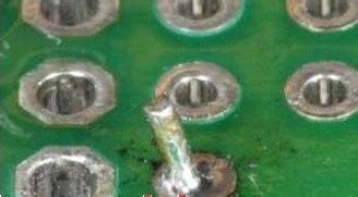
1. Cold Solder Joints
Cold solder joints occur when the solder does not melt completely, resulting in a weak and unreliable connection. This can happen due to insufficient heat, improper solder alloy, or contamination of the soldering iron tip or the PCB surface.
To avoid cold solder joints:
– Ensure that the soldering iron is at the correct temperature (typically 300-350°C)
– Use the appropriate solder alloy for the application
– Clean the soldering iron tip and the PCB surface before soldering
2. Bridging
Bridging occurs when excess solder accidentally connects two or more adjacent pins or pads, creating a short circuit. This can happen when too much solder is applied or when the soldering iron tip is too large for the component.
To avoid bridging:
– Use the appropriate amount of solder
– Choose a soldering iron tip that fits the component size
– Inspect the soldered joints for any bridging and remove excess solder using a solder wick or desoldering pump

3. Tombstoning
Tombstoning, also known as the “Manhattan effect,” happens when a surface-mount component stands up on one end due to uneven heating or an imbalance in the solder paste. This can occur when the component is misaligned or when there is a difference in the solder paste volume on the pads.
To avoid tombstoning:
– Ensure proper alignment of the component during placement
– Apply an even amount of solder paste on the pads
– Use a reflow oven with a well-controlled temperature profile

4. Solder Balls
Solder balls are small, spherical balls of solder that can form on the PCB surface during the soldering process. They can cause short circuits and affect the reliability of the electronic device. Solder balls can occur due to excessive solder paste, improper reflow oven settings, or contamination.
To avoid solder balls:
– Apply the appropriate amount of solder paste
– Optimize the reflow oven settings, such as the temperature profile and conveyor speed
– Maintain a clean and contamination-free environment during the soldering process

5. Insufficient Solder
Insufficient solder can lead to weak and unreliable connections, causing intermittent failures or open circuits. This can happen when too little solder is applied or when the soldering iron temperature is too low.
To avoid insufficient solder:
– Apply the appropriate amount of solder to create a proper solder joint
– Ensure that the soldering iron is at the correct temperature
– Inspect the soldered joints visually and using X-ray imaging for critical applications
6. Lifted Pads
Lifted pads occur when the copper pad on the PCB separates from the board during the soldering process. This can happen due to excessive heat, improper soldering technique, or poor PCB design.
To avoid lifted pads:
– Use the appropriate soldering iron temperature and avoid excessive heat
– Follow proper soldering techniques, such as applying gentle pressure and avoiding excessive dwell time
– Ensure that the PCB design has adequate pad size and copper thickness
7. Solder Wicking
Solder wicking, also known as capillary action, occurs when molten solder flows away from the intended joint and along the component lead or PCB trace. This can result in insufficient solder at the joint and create a weak connection.
To avoid solder wicking:
– Apply the appropriate amount of solder
– Use a soldering iron with a fine tip to control the solder flow
– Design the PCB with proper spacing between components and traces
8. Flux Residue
Flux is a chemical agent used to remove oxides and improve solder wettability during the soldering process. However, if the flux is not cleaned properly after soldering, it can leave a residue on the PCB surface. Flux residue can cause corrosion, affect the appearance of the board, and degrade the performance of the electronic device.
To avoid flux residue:
– Use a no-clean flux that leaves minimal residue
– Clean the PCB thoroughly after soldering using an appropriate cleaning solution
– Inspect the PCB for any remaining flux residue and repeat the cleaning process if necessary
9. Overheating Components
Overheating components during the soldering process can cause damage, such as cracking, delamination, or degradation of the component’s performance. This can happen when the soldering iron temperature is too high or when the soldering time is too long.
To avoid overheating components:
– Use the appropriate soldering iron temperature for the component and PCB material
– Minimize the soldering time by applying heat efficiently and removing the soldering iron promptly
– Use a heat sink or thermal relief design to dissipate heat from sensitive components
10. Solder Mask Damage
Solder mask is a protective coating applied to the PCB surface to prevent solder from adhering to unwanted areas. Damage to the solder mask can occur due to excessive heat, improper handling, or chemical exposure during the soldering process.
To avoid solder mask damage:
– Use the appropriate soldering iron temperature and avoid excessive heat
– Handle the PCB carefully to prevent scratches or abrasions on the solder mask
– Avoid exposure to harsh chemicals during the soldering process
11. Incorrect Component Orientation
Incorrect component orientation can lead to malfunction or damage to the electronic device. This can happen due to human error during manual assembly or improper programming of automated assembly equipment.
To avoid incorrect component orientation:
– Use clear and unambiguous markings on the PCB and components to indicate the correct orientation
– Implement a quality control process to verify the correct orientation of components before soldering
– Use automated assembly equipment with vision systems to detect and correct orientation errors
12. Whiskers
Whiskers are thin, hair-like metallic growths that can form on the surface of soldered joints over time. They can cause short circuits and reliability issues in electronic devices. Whiskers are more common in lead-free solder alloys and can be influenced by factors such as stress, temperature, and humidity.
To avoid whiskers:
– Use solder alloys with a lower propensity for whisker formation, such as tin-lead alloys or tin-silver-copper alloys with additional elements like nickel or bismuth
– Apply conformal coatings or encapsulation to protect the soldered joints from environmental factors
– Design the PCB and components to minimize mechanical stress and thermal expansion mismatches
13. Solder Joint Fatigue
Solder joint fatigue occurs when the solder joint experiences repeated stress due to thermal cycling, vibration, or mechanical loading. Over time, the solder joint can crack or fail, leading to intermittent or permanent failures in the electronic device.
To avoid solder joint fatigue:
– Design the PCB and components to minimize thermal expansion mismatches and mechanical stress
– Use solder alloys with good mechanical properties and fatigue resistance, such as tin-silver-copper alloys
– Implement strain relief features, such as underfill or conformal coatings, to support the solder joints
14. Contamination
Contamination of the PCB or components during the soldering process can lead to poor solder joint quality, corrosion, or electrical failures. Contaminants can include dust, dirt, oils, or chemical residues.
To avoid contamination:
– Maintain a clean and controlled environment during the soldering process
– Use clean and high-quality solder, flux, and cleaning solutions
– Handle the PCB and components with gloves or tweezers to prevent contamination from skin oils
– Clean the PCB and components thoroughly before and after soldering
15. Incomplete Hole Fill
Incomplete hole fill can occur in through-hole soldering when the solder does not fully fill the plated through-hole, creating a void or gap. This can result in a weak or unreliable connection, especially in high-vibration or thermal cycling environments.
To avoid incomplete hole fill:
– Use the appropriate soldering iron temperature and tip size for the through-hole size
– Apply sufficient solder to fill the hole completely
– Use a soldering technique that promotes good solder flow, such as the “drag soldering” method
– Inspect the soldered joints visually or using X-ray imaging to ensure complete hole fill
FAQ
Q: What is the most common PCB Soldering problem?
A: Cold solder joints are one of the most common PCB Soldering Problems. They occur when the solder does not melt completely, resulting in a weak and unreliable connection.
Q: Can PCB soldering problems be detected visually?
A: Many PCB soldering problems, such as bridging, insufficient solder, and solder balls, can be detected visually. However, some issues, like internal voids or incomplete hole fill, may require X-ray imaging for detection.
Q: How can I prevent PCB soldering problems?
A: To prevent PCB soldering problems, use the appropriate soldering iron temperature and tip size, apply the correct amount of solder, maintain a clean and controlled environment, and follow proper soldering techniques. Additionally, ensure that the PCB design is optimized for manufacturability and reliability.
Q: What are the consequences of PCB soldering problems?
A: PCB soldering problems can lead to various issues, such as intermittent failures, short circuits, open circuits, and degraded performance of the electronic device. In some cases, soldering problems can even cause permanent damage to the components or the PCB.
Q: How can I repair PCB soldering problems?
A: The repair method for PCB soldering problems depends on the specific issue. Some problems, like bridging or excess solder, can be corrected using a solder wick or desoldering pump. Other issues, such as lifted pads or damaged components, may require more advanced repair techniques or replacement of the affected parts. In some cases, the best solution may be to rework the entire PCB.
| PCB Soldering Problem | Cause | Prevention |
|---|---|---|
| Cold Solder Joints | Insufficient heat, improper solder alloy, contamination | Use correct temperature, appropriate solder alloy, clean soldering iron tip and PCB surface |
| Bridging | Excess solder, large soldering iron tip | Use appropriate amount of solder, choose soldering iron tip that fits component size |
| Tombstoning | Uneven heating, imbalance in solder paste | Ensure proper component alignment, apply even amount of solder paste, use well-controlled reflow |
| Solder Balls | Excessive solder paste, improper reflow settings, contamination | Apply appropriate amount of solder paste, optimize reflow settings, maintain clean environment |
| Insufficient Solder | Too little solder, low soldering iron temperature | Apply appropriate amount of solder, ensure correct soldering iron temperature |
In conclusion, PCB soldering problems can have significant impacts on the reliability and functionality of electronic devices. By understanding the common issues and their causes, manufacturers can take steps to prevent or mitigate these problems. Proper soldering techniques, equipment maintenance, and quality control processes are essential for achieving high-quality PCB soldering results. By addressing these 15 common PCB soldering problems, manufacturers can improve the overall quality and reliability of their electronic products.


Leave a Reply