Introduction
Printed circuit boards (PCBs) are essential components in nearly all modern electronics. They provide the foundation for mounting and interconnecting electronic components using conductive copper traces etched from copper sheets laminated onto a non-conductive substrate.
While the most common PCB material is FR-4 glass epoxy, polyimide (PI) has emerged as an attractive high-performance alternative substrate material. Polyimide PCBs offer exceptional thermal, chemical and mechanical properties that make them ideal for applications requiring durability under extreme conditions.
This article will examine the properties, applications and manufacturing processes of rigid polyimide PCBs. Key topics include:
- Properties of polyimide PCB materials
- Advantages over FR-4 and other substrates
- Applications demanding high heat, chemical resistance
- Rigid vs. flex PI PCBs
- Manufacturing processes – fabrication, lamination, etching
- Quality testing and specifications
- Cost considerations
Understanding polyimide PCB technology enables designers to select the optimal material for their application needs and work effectively with PCB manufacturers during the fabrication process.
Properties of Rigid Polyimide PCB Materials
Polyimide is a thermoset plastic polymer material belonging to a class known as polyimides. It is formed by combining two monomers containing imide functional groups. Through polycondensation and imidization reactions, long polyimide polymer chains are produced.
Some key properties of polyimide PCB materials:
- High thermal stability – Glass transition temperature over 300°C. Withstands peak temperatures up to 500°C. Low thermal expansion.
- Chemical resistance – Inert to most solvents, acids, alkalis. Resists oxidizing environments.
- Mechanical strength – Tensile strength 70-100 MPa. Flexible but dimensions stable. Withstands vibration, shock.
- Electrical insulation – High resistivity >10^15 ohm-cm. Low dielectric constant 3.4-3.6.
- Flame resistance – Highly fire retardant with oxygen index 55-60%. Low smoke emission.
These exceptional properties make polyimide well-suited for many demanding applications, especially under extreme temperature, chemical and mechanical stress. Polyimide PCBs outperform conventional FR-4 glass epoxy boards.
| Property | Polyimide | FR-4 Glass Epoxy |
|---|---|---|
| Glass Transition Temperature | >300°C | 130-180°C |
| Max Operating Temperature | 260°C (short term 500°C) | 105°C |
| Thermal Expansion Coefficient | 3-5 ppm/K | 12-20 ppm/K |
| Tensile Strength | 70-100 MPa | 35-40 MPa |
| Flexural Strength | 100-150 MPa | 10-20 MPa |
| Water Absorption | 0.4% | 0.15-0.35% |
| Chemical Resistance | Excellent – inert | Fair – susceptible to acids/alkalis |
| Dielectric Constant | 3.4-3.6 | 4.5-4.9 |
| Loss Tangent | 0.002-0.005 | 0.015-0.025 |
Applications of Rigid Polyimide PCBs
The outstanding thermal, mechanical and electrical insulation properties of polyimide make it ideal for electronics designed for high reliability in harsh environments.
Some major application areas include:
High Temperature Electronics
- Aerospace and aviation – engine controls, guidance systems, avionics
- Automotive – electronics under the hood, EV/HEV circuits
- Oil and gas – downhole drilling equipment
- Medical – sterilization equipment, analyzers
Polyimide PCBs withstand prolonged exposure to temperatures exceeding 260°C required in these applications.
High Frequency/High Speed Circuits
- Telecom infrastructure – 5G networks, base stations, switches
- Defense systems – radars, communications
- Scientific equipment – particle accelerators, satellites
Polyimide’s low dielectric constant and loss tangent support high frequency microwave circuits up to 77 GHz and high speed digital circuits.
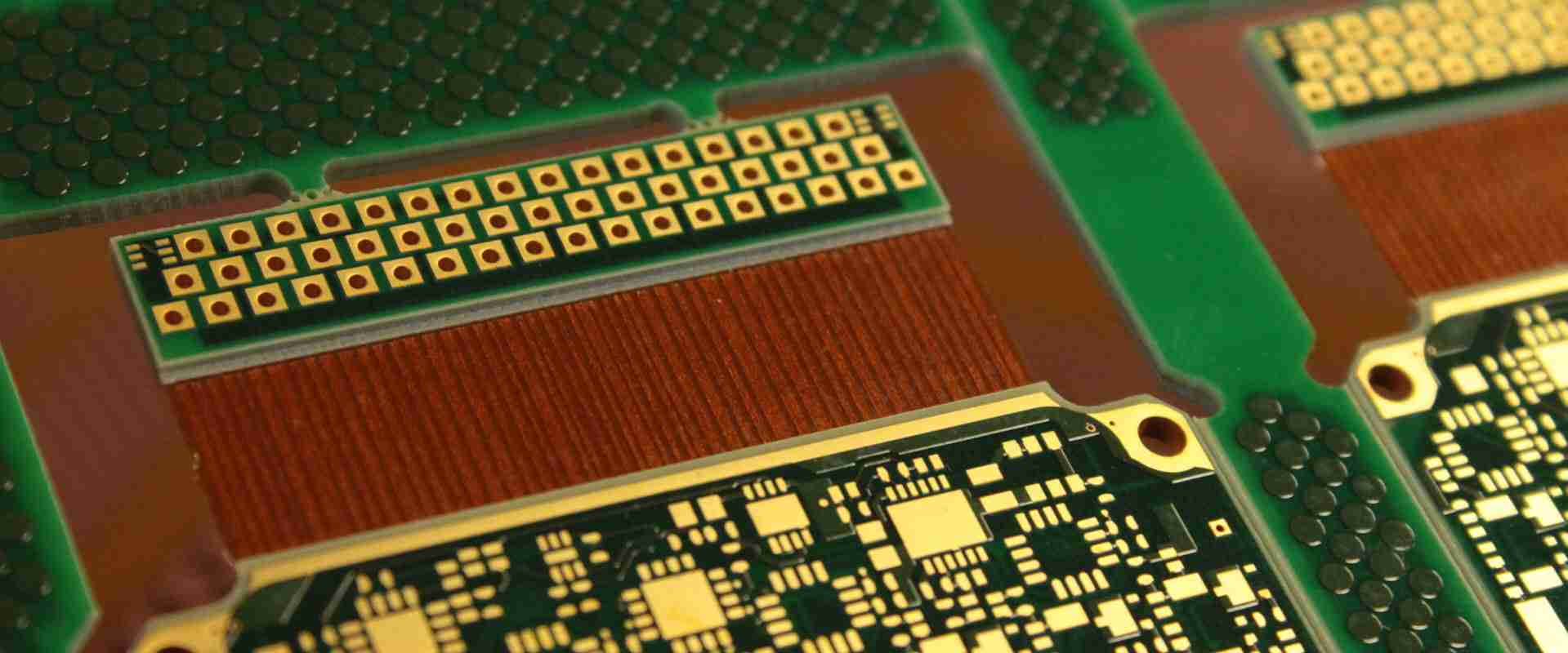
Flexible and Rigid-Flex PCBs
- Consumer electronics – phones, laptops, wearables
- Automotive – cameras, sensors, infotainment displays
- Medical – imaging, implanted devices
Polyimide’s flexibility allows it to be used standalone or bonded to rigid PCBs for flexible and rigid-flex designs.
Chemically Corrosive Environments
- Industrial – sensors and controls exposed to acids, alkalis, solvents
- Aerospace – systems exposed to fuels and oxidizers
Polyimide’s chemical resistance allows circuit operation without corrosion or deterioration.
High Mechanical Stress Applications
- Automotive – engine control units subject to vibration
- Aerospace – avionics subject to vibration and shock
- Defense – military systems subject to shock/vibration
Polyimide’s high tensile and flexural strength prevents cracking and failure.
Others
- Low smoke/toxicity – for confined electronic equipment to ensure safety
- Radiation hardened – for space and nuclear applications
- Flame retardant – to meet safety standards
This wide range makes polyimide PCBs ideal for mission-critical electronics expected to perform reliably under extreme conditions.
Rigid vs. Flexible Polyimide PCBs
Polyimide PCBs are available in both rigid and flexible circuit designs.
Rigid polyimide boards consist of polyimide laminated onto both sides of a copper layer. They provide the exceptional thermal, chemical and mechanical resilience associated with polyimide. Rigid boards are ideal for applications requiring:
- Stable dimensions for precision circuitry
- Easy integration into enclosures and chassis
- Capability to withstand flexing
- High layer counts and complex circuit geometries
Flexible polyimide boards consist of polyimide substrate only, without bonding to a rigid layer. Benefits include:
- Can be dynamically flexed and folded
- Thinner form factors – as low as 25 microns
- Light weight – ideal for small devices
- Lower costs compared to rigid flex
- 3D assembly – can conform to complex shapes
Flexible circuits are ideal when the board itself requires dynamic or static bending. This includes folding displays, rollable solar films, and wearable devices.
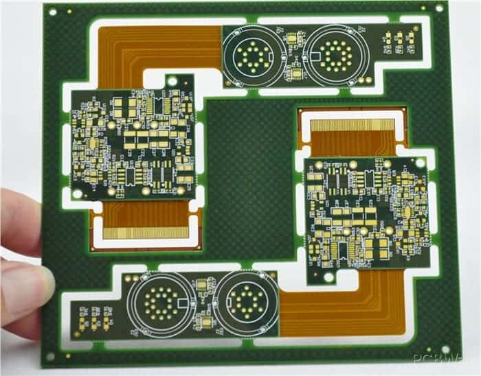
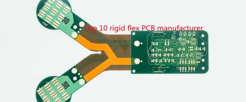
Rigid-flex PCBs combine both rigid and flexible polyimide materials into one circuit board. This allows:
- Rigid sections for component mounting and complex circuits
- Dynamic or static flexing in specified areas
- 3D shaping – curves, folds, branching
- Layer transitions between flexible and rigid sections
Rigid-flex is ideal for complex devices like foldable phones, medical snake catheters, and shaped wearable electronics.
Manufacturing Processes for Rigid Polyimide PCBs
Fabricating high quality polyimide PCBs requires specialized manufacturing processes tailored to the material’s unique properties.
Board Materials
The polyimide core substrate can be supplied in sheets or as a liquid polyamic acid resin precursor. Common branded versions include DuPont Pyralux and Kaneka Glastic. Reinforcements such as fiberglass or metal foils may be incorporated.
The stacked material layers in a rigid PI PCB include:
- Polyimide dielectric substrate core
- Copper foil conductors (typical 1 oz/ft2 or 2 oz/ft2)
- Adhesion promoting chemical treatments
Fabrication
Polyimide PCBs leverage many of the same fabrication processes as conventional PCBs, but each stage requires optimization for polyimide’s thermal and chemical characteristics.
Lamination – Individual layers are stacked and bonded using high temperature and pressure. Temperatures approach 400°C to fully imidize the polyamic acid into polyimide.
Drilling – Holes are mechanically drilled or laser drilled. Plasma etching clears debris. Permanganate desmear removes resin smear.
Metallization – Holes are plated with copper and a chemical microetch enhances adhesion.
Photolithography – A photoresist mask is imaged and developed to define the copper circuit pattern.
Etching – Exposed copper is chemically etched away leaving only the desired conductor traces.
Stripping – The remaining photoresist is chemically stripped.
Solder mask – A masking material coats the board excluding solder pads.
Finishing – Organic solderability preservatives (OSPs) are applied to protect copper traces from oxidation.
Testing – Rigorous electrical testing checks for shorts, opens and impedance.
Metal Core PI PCBs use a metal substrate like aluminum or copper instead of polyimide. The metal core provides enhanced thermal conductivity.
Quality Testing and Specifications
Comprehensive testing ensures polyimide PCBs meet stringent quality and performance standards:
- IPC testing – Industry standards for PCB acceptability (IPC-A-600) and design (IPC-2221) are followed.
- Dimensional accuracy – Optical and electrical measurements confirm trace widths, hole sizes, and line spacing.
- Electrical testing – Shorts, opens, impedance, dielectric withstand voltage, and leakage current are tested.
- Thermal stress – Testing under temperature cycling, moisture, vibration and other stresses.
- Coupon evaluations – Test coupons with daisy chains gauge process capabilities.
- Test points – Test points added for checking key voltages or impedances.
- Certifications – Quality systems are certified to AS9100, ISO 9001, or other standards.
Military and aerospace customers often impose additional requirements described in performance specifications like MIL-PRF-31032 or J-STD-020.
Cost Considerations for Polyimide PCBs
Polyimide PCBs cost more than conventional FR-4 boards but offer substantial performance advantages justifying the price premium in appropriate applications.
Factors affecting polyimide PCB costs:
- Board materials – polyimide dielectrics inherently cost more than FR-4.
- Fabrication processes – specialized high-temperature steps increase costs.
- Lower volume – polyimide’s specialized niche limits economies of scale.
- Design complexity – high layer counts, fine features, dense circuitry increase costs.
- Certification – meeting military and aerospace standards imposes added costs.
- Quality controls – extensive testing and inspection adds cost.
- Location – local vs. overseas board sourcing impacts price.
However, polyimide PCBs enable product performance and capabilities not attainable with FR-4 in high reliability applications. The value derived often offsets the higher initial component costs.
Conclusion
Polyimide PCB technology enables electronics to survive extreme environments and operate reliably at high temperatures, frequencies, speeds and mechanical stresses. As high performance requirements in industries like aerospace, automotive, telecom and medical electronics continue advancing, polyimide PCBs provide an enabling substrate technology where FR-4 glass epoxy boards fall short. By understanding polyimide’s specialized properties and manufacturing processes, PCB designers and engineers can effectively apply this technology to achieve the most demanding application requirements.
FQA
What are some key differences between polyimide and FR-4 PCBs?
Some key differences between polyimide PCBs versus standard FR-4 PCBs include:
- Higher heat resistance – polyimide can withstand over 260°C continuously versus only 105°C for FR-4.
- Greater dimensional stability – low thermal expansion minimizes thermal stress effects.
- Higher frequency support – lower dielectric constants enable high frequency microwave circuits.
- Better chemical resistance – inert to most solvents, acids, alkalis unlike FR-4.
- Higher flexural strength – withstands vibration, shock, and bending forces.
- Lower moisture absorption – absorbs very little humidity compared to FR-4.
Is polyimide suitable for multilayer PCBs? What are the limitations?
Polyimide can definitely be used for multilayer PCBs to gain the benefits of its properties in complex boards. Some of the limitations include:
- Layer count – typically not more than 12-14 layers versus >20 for FR-4.
- Via formation – drilling and plating small vias is challenging.
- Thermal management – thicker metal cores help dissipate heat for high layer counts.
- Costs – production costs rise rapidly for high layer designs.
- Aspect ratios – high density interconnects have lower achievable aspect ratios.
So polyimide multilayer PCBs tend to be used where the layer count is moderately high, typically for 6-10 layer boards maximum.
What are some examples of rigid-flex polyimide PCB applications?
Some examples of products utilizing rigid-flex polyimide PCBs include:
- Foldable smartphones – rigid PCBA sections joined by flexing display.
- Wearable devices – rigid circuitry combined with flexible straps.
- Medical catheters – rigid tips for sensors joining flexible narrow tubes.
- Robotics – rigid controller boards with flexible interconnects to joints.
- Automotive camera – combine rigid sensor board with flexible cabling.
- Laptops – rigid motherboard and flexible interconnects to display.
- Avionics – rigid boards with dynamic flexing cables for control surfaces.
Polyimide rigid-flex allows optimizing PCB mechanical requirements in a single component.
What are some best practice design rules for laying out polyimide PCBs?
Some polyimide PCB layout design rules and guidelines include:
- Match coefficients of thermal expansion – minimize interfaces between PI and other materials.
- Increase line spacing – match wider trace/space rules used for polyimide fabrication.
- Increase hole sizes – allow for typically lower aspect ratio vias.
- Minimize acute angles – improve chemical etching using 45 degree trace angles.
- Allow for greater board thickness – polyimide dielectric layers are thicker than FR4.
- Adjust impedance rules – lower dielectric constant changes impedance calculations.
- Review DFM guidelines – seek manufacturer design for manufacturability input.
- Perform thermal analysis – ensure thermal dissipation in final system assembly.
Early collaboration with the board fabrication shop is highly recommended.
What testing standards are used to qualify aerospace and defense grade polyimide PCBs?
Some key testing standards used for qualifying high reliability polyimide PCBs include:
- IPC-6012 – Qualification and Performance Specification for Rigid Printed Boards
- MIL-PRF-31032 – Printed Circuit Board General and Base Materials Specification
- J-STD-020 – Joint Industry Standard for Cable and Wire Harness Assemblies
- IPC-TM-650 – Test Methods Manual for characterizing PCB materials
- IPC-A-600 – Acceptability of Printed Circuit Boards minimum quality requirements
- IPC-6018 – Qualification and Performance Specification for High Frequency (Microwave) Printed Boards
Extensive lot sampling, environmental stress testing, design verification, and quality system requirements aim to ensure robust performance in demanding defense and aerospace applications.


Leave a Reply