Introduction to the lm324 Quad Op-Amp
The lm324 is a popular and versatile quad operational amplifier (op-amp) integrated circuit. It contains four independent high-gain op-amps in a single package. The lm324’s key features include:
- Wide supply voltage range: 3V to 32V (or ±1.5V to ±16V)
- Low supply current drain: 700 µA
- Unity gain bandwidth: 1 MHz
- Input common-mode voltage range includes ground
- Differential input voltage range equal to maximum supply voltage
- Large output voltage swing: 0V to V+ – 1.5V
These characteristics make the lm324 suitable for a wide range of analog applications such as signal conditioning, active filtering, mathematical operations, and voltage comparison. It is commonly used in battery-powered devices due to its ability to operate with single supplies down to 3V.
lm324 Pinout and Pin Functions
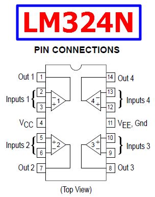
The lm324 comes in a 14-pin dual in-line package (DIP). Here is the pinout:
| Pin | Function |
|---|---|
| 1 | Output 1 |
| 2 | Inverting Input 1 |
| 3 | Non-Inverting Input 1 |
| 4 | V- (Negative Supply) |
| 5 | Non-Inverting Input 2 |
| 6 | Inverting Input 2 |
| 7 | Output 2 |
| 8 | Output 3 |
| 9 | Inverting Input 3 |
| 10 | Non-Inverting Input 3 |
| 11 | V+ (Positive Supply) |
| 12 | Non-Inverting Input 4 |
| 13 | Inverting Input 4 |
| 14 | Output 4 |
The four op-amps are completely independent but share common power supply pins (V+ and V-). The inputs and output of each op-amp are brought out to separate pins.
Power Supply
The lm324 can be powered from either a single positive voltage supply (3V to 32V) or dual supplies (±1.5V to ±16V). When using a single supply, connect V- to ground. Bypass the power supply pins with 0.1 µF ceramic capacitors close to the IC for stability.
Input and Output
Each op-amp has an inverting (-) and non-inverting (+) input. The output voltage depends on the difference between these inputs amplified by the op-amp’s gain.
The inputs are high impedance (typical input resistance >1M ohm), allowing them to minimally load the signal source. The output is low impedance and can typically source or sink up to 20 mA.

Basic Op-Amp Configurations with the lm324
The lm324’s four op-amps can be used independently in various standard op-amp circuits. Here are some of the most common configurations:
Unity Gain Buffer (Voltage Follower)
A voltage follower has a voltage gain of 1, with the output voltage equal to the input voltage. It is used to buffer a high impedance signal source from a low impedance load.
To configure an lm324 op-amp as a unity gain buffer:
1. Connect the op-amp’s output directly to its inverting input
2. Apply the input signal to the non-inverting input
Non-Inverting Amplifier
A non-inverting amplifier has a voltage gain greater than 1 and maintains the same polarity between input and output. The gain is set by the ratio of two resistors.
To configure a non-inverting amplifier:
1. Connect a resistor (R1) between the op-amp’s inverting input and ground
2. Connect a feedback resistor (R2) between the inverting input and output
3. Apply the input signal to the non-inverting input
The voltage gain (Av) is given by: Av = 1 + (R2 / R1)
Inverting Amplifier
An inverting amplifier has a voltage gain greater than 1 but inverts the polarity of the input signal. Like the non-inverting amp, gain is set by a resistor ratio.
To configure an inverting amplifier:
1. Connect the op-amp’s non-inverting input to ground
2. Connect an input resistor (R1) in series with the signal source to the inverting input
3. Connect a feedback resistor (R2) between inverting input and output
The voltage gain is: Av = -(R2 / R1)
Differential Amplifier
A differential amplifier amplifies the voltage difference between two input signals while rejecting any common-mode voltages. It has two inputs and one output.
Here is one way to configure a differential amplifier using an lm324 op-amp:
- Apply input signal 1 to the non-inverting input through resistor R1
- Apply input signal 2 to the inverting input through R2
- Connect a resistor (R3) between the inverting input and ground
- Connect a feedback resistor (R4) between inverting input and output
For best performance, use 1% tolerance resistors with R1=R3 and R2=R4.
The differential gain is: Ad = R4/R3
The common-mode gain is: Acm = R4/(R1+R2)
These are just a few of the most common op-amp circuits that can be built with the lm324. By combining multiple op-amps in more complex feedback networks, a diverse range of linear and non-linear analog functions can be realized including summing amps, integrators, differentiators, filters, oscillators, precision rectifiers, and more.

lm324 Comparator Circuits
One of the most useful applications of op-amps like the lm324 is as voltage comparators. A comparator circuit compares an input voltage to a reference voltage and outputs a binary signal indicating which is greater.
Basic comparators have no feedback from output to input, so the full open-loop gain (AOL ≈ 100,000) of the op-amp is applied. This makes the output rapidly switch between the positive and negative supply rails as the differential input crosses through zero.
Important parameters for a comparator op-amp are:
– High gain for fast switching
– Low Vos (input offset voltage)
– Fast slew rate
– Compatible with single-supply operation
The lm324 meets these requirements well in a low-cost quad package, making it a popular choice for multi-channel comparator circuits.
Inverting and Non-Inverting Comparators
Here are two simple lm324 comparator circuits:
Inverting Comparator
- Connect VREF to the non-inverting input
- Connect VIN to the inverting input through R1
- Leave the output unconnected (open loop)
If VIN > VREF, VOUT goes low (≈ V-)
If VIN < VREF, VOUT goes high (≈ V+)
Non-Inverting Comparator
- Connect VREF to the inverting input
- Connect VIN to the non-inverting input
- Leave output unconnected
If VIN > VREF, VOUT goes high
If VIN < VREF, VOUT goes low
Hysteresis
A potential issue with the basic comparators shown above is output instability and oscillation when the input signal is noisy and hovers close to VREF. The op-amp output can repeatedly switch back and forth between states.
To prevent this, hysteresis or a “deadband” is often added to a comparator using positive feedback. This introduces two switching thresholds, one for the low-to-high transition and another for high-to-low. The difference between the thresholds is the hysteresis voltage (VHYS).
Here is an inverting comparator with hysteresis:
With hysteresis, the comparator thresholds are:
VTL = VREF (R1 / (R1 + R2))
VTH = VREF / (R1 / (R1 + R2))
VHYS = VTH – VTL
Hysteresis is essential in applications like slow moving input signals and noisy environments to prevent output chattering. The tradeoff is reduced sensitivity compared to a zero-hysteresis comparator.

lm324 Active Filters
Active filters are another strength of the versatile lm324. By combining the op-amp with resistors and capacitors in a feedback network, various high-pass, low-pass and band-pass filters can be realized.
Compared to passive RLC filters, active filters offer key advantages:
– Gain (no insertion loss)
– Easy and wide ranging tuning of cutoff frequency (fc)
– High input impedance and low output impedance
– No loading of signal source or filter stages
– Smaller size (no inductors)
A common active filter topology is the Sallen-Key, which supports low-pass, high-pass and band-pass responses with gain. Here is a 2nd order unity-gain Sallen-Key low-pass filter:
The filter cutoff frequency is: fc = 1 / (2π√(R1R2C1C2))
By cascading multiple 2nd order stages, higher order filters (4th order, 6th order, etc.) with steeper rolloff can be designed. The lm324 quad package is ideal for this. Putting the filter design equations into a spreadsheet allows quick computation of component values for any desired cutoff frequency.
For variable cutoff, replace R1 and R2 with a dual-gang potentiometer. Or for voltage controlled cutoff, replace R1/R2 with an analog multiplier IC like the MPY634. This is how many voltage controlled filters (VCFs) work.
A couple more examples of lm324 active filter circuits:
lm324 Limitations and Alternatives
While the lm324 is a dependable and widely used op-amp, it’s important to understand its limitations. The lm324 is based on an older bipolar design, so it can’t compete with modern op-amps in some regards:
-
Limited bandwidth: The 1 MHz gain-bandwidth product (GBP) of the lm324 restricts it to low frequency applications. For audio and ultrasonic circuits, consider faster op-amps like the NE5532 or LM833.
-
High input bias and offset current: The lm324’s bipolar input stage draws significant bias current which can cause errors at high impedances. Its typical 2mV input offset voltage also creates DC error. For precision apps, use a JFET or CMOS input op-amp like TL074.
-
High noise: The lm324 is relatively noisy, producing about 40 nV/√Hz. For low noise circuits, use an op-amp like the LT1124 or OP27.
-
Low slew rate: At 0.5 V/µs, the lm324 is quite slow. This can distort high amplitude high frequency signals. Faster op-amps like the ADA4898 provide much higher slew rates.
-
Non-rail-to-rail I/O: Even with single supply operation, the lm324 inputs and outputs cannot swing all the way to V+ and V-. For true rail-to-rail operation, use a CMOS op-amp like the MCP6004.
That said, for non-critical low frequency analog circuits operating in the audio range and below, the lm324 is usually adequate. Its low cost and availability in a convenient quad package make it an excellent choice for beginners learning about analog circuits and op-amps.
Some common lm324 alternatives and their key specifications:
| Part # | Type | GBP | Vos | Ib | Noise | SR | Price | Notes |
|---|---|---|---|---|---|---|---|---|
| LM324 | BJT | 1.2 MHz | 2 mV | 20 nA | 40 nV/√Hz | 0.5 V/µs | $0.50 | – |
| LM358 | BJT | 1.1 MHz | 2 mV | 20 nA | 40 nV/√Hz | 0.3 V/µs | $0.40 | Dual |
| TL074 | JFET | 3 MHz | 3 mV | 0.2 nA | 18 nV/√Hz | 13 V/µs | $0.75 | Quad |
| OPA4131 | CMOS | 1 MHz | 0.1 mV | 1 pA | 27 nV/√Hz | 2 V/µs | $1.00 | R2R Quad |
| NE5532 | BJT | 10 MHz | 0.5 mV | 200 nA | 5 nV/√Hz | 9 V/µs | $0.65 | Audio Dual |
Frequently Asked Questions (FAQ)
Q: Can the lm324 be used with a single power supply?
A: Yes, the lm324 is designed to work with single supplies from 3V to 32V as well as dual supplies from ±1.5V to ±16V. For single supply operation, connect the V- pin to ground.
Q: What is the maximum supply voltage for the lm324?
A: The lm324’s absolute maximum supply voltage is 32V for single supply or ±16V for dual supplies. However, the recommended maximums for best performance are 30V and ±15V.
Q: How much current can the lm324 output source or sink?
A: The lm324 can typically source or sink up to 20 mA continuous current. However, it’s best to limit output current to under 10 mA for optimal linearity.
Q: Does the lm324 have short circuit protection?
A: Yes, the lm324 has both momentary and continuous output short circuit protection. The output can be shorted to either supply rail without damage. However, to prevent overheating, limit the duration of shorts and the package temperature.
Q: What is the input voltage range of the lm324?
A: One key feature of the lm324 is that the input common-mode voltage range extends down to the negative rail (V-), allowing it to be used in single supply circuits where the input may go all the way to ground (0V). The maximum input differential voltage (between +Vin and -Vin) should not exceed the supply voltage.


Leave a Reply