Introduction to Flex Sensors
Flex sensors, also known as bend sensors, are resistive sensors that change their resistance when bent or flexed. They are commonly used in various applications such as wearable devices, robotics, and gaming controllers to measure the amount of bending or flexing. In this article, we will explore the working principle of flex sensors and how to interface them with an Arduino microcontroller.
What is a Flex Sensor?
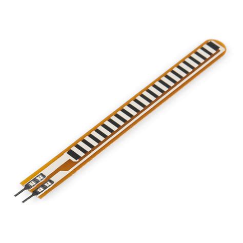
A flex sensor is a thin, flexible strip that contains a layer of conductive material, typically carbon or polymer ink, printed on a flexible substrate. As the sensor is bent or flexed, the conductive layer experiences stress, which causes a change in its electrical resistance. The more the sensor is bent, the higher the resistance becomes.
Flex sensors come in various sizes and resistance ranges. The most common sizes are 2.2 inches and 4.5 inches, with resistance ranges of 10kΩ to 50kΩ when flat and up to 200kΩ when bent at a 90-degree angle.
Flex Sensor Construction
A typical flex sensor consists of the following components:
- Flexible substrate: A thin, flexible material, such as polyester or polyimide, serves as the base for the sensor.
- Conductive ink: A layer of conductive material, usually carbon or polymer ink, is printed on the substrate. This layer acts as a variable resistor when the sensor is bent.
- Protective layer: A clear, flexible protective layer covers the conductive ink to prevent damage and enhance durability.
The conductive ink is printed in a pattern that allows for a predictable change in resistance when the sensor is bent. The resistance change is proportional to the degree of bending, enabling the measurement of the flex angle.
Flex Sensor Working Principle
The working principle of a flex sensor is based on the piezoresistive effect, which is the change in electrical resistance of a material when subjected to mechanical stress. In the case of a flex sensor, the mechanical stress is caused by bending or flexing the sensor.
Piezoresistive Effect
When a flex sensor is bent, the conductive ink layer experiences compression on the inside of the bend and tension on the outside. This stress causes the conductive particles in the ink to move closer together or further apart, resulting in a change in the electrical resistance of the material.
The relationship between the resistance change and the bend angle is not perfectly linear, but it can be approximated using a polynomial function. The exact characteristics of the resistance change depend on the specific flex sensor and its construction.
Resistance Calculation
To calculate the resistance of a flex sensor at a given bend angle, you can use the following equation:
R_flex = R_flat * (1 + (K_flex * θ))
Where:
– R_flex is the resistance of the flex sensor at the given bend angle (in ohms)
– R_flat is the resistance of the flex sensor when flat (in ohms)
– K_flex is the flex factor, a constant that depends on the specific flex sensor (typically provided by the manufacturer)
– θ is the bend angle (in radians)
For example, if a flex sensor has a flat resistance of 10kΩ and a flex factor of 0.5, and it is bent at a 90-degree angle (π/2 radians), the resistance would be:
R_flex = 10kΩ * (1 + (0.5 * π/2)) ≈ 17.85kΩ

Interfacing Flex Sensor with Arduino
To interface a flex sensor with an Arduino, you need to create a simple voltage divider circuit. This circuit allows you to measure the change in resistance of the flex sensor and convert it into a voltage that can be read by the Arduino’s analog input.
Flex Sensor Circuit
The flex sensor circuit consists of the following components:
- Flex sensor
- Fixed resistor (usually 10kΩ)
- Arduino board
- Breadboard
- Jumper wires
The circuit diagram for the Flex Sensor Interface is as follows:
            Flex Sensor
      +-----------/\/\/\-----------+
      |                            |
     Vcc                        Arduino
      |                       Analog Pin
      +---[10kΩ]---+--------+
                   |        |
                  GND     GND
In this circuit, the flex sensor and the fixed resistor form a voltage divider. The Arduino’s analog input pin measures the voltage at the point between the flex sensor and the fixed resistor.
Arduino Code
To read the flex sensor value and convert it into a bend angle, you can use the following Arduino code:
const int FLEX_PIN = A0; // Pin connected to the flex sensor

// Resistance values for flat and 90-degree bend
const float FLAT_RESISTANCE = 10000.0; // Resistance when flat (adjust as needed)
const float BEND_RESISTANCE = 20000.0; // Resistance at 90° bend (adjust as needed)

void setup() {
  Serial.begin(9600); // Initialize serial communication
}

void loop() {
  int flexValue = analogRead(FLEX_PIN); // Read the analog value
  float voltage = flexValue * (5.0 / 1023.0); // Convert to voltage

  float resistance = FLAT_RESISTANCE * (5.0 / voltage - 1.0); // Calculate resistance

  float angle = map(resistance, FLAT_RESISTANCE, BEND_RESISTANCE, 0, 90); // Map resistance to angle

  Serial.print("Flex Sensor Value: ");
  Serial.print(flexValue);
  Serial.print(" | Voltage: ");
  Serial.print(voltage);
  Serial.print(" V | Resistance: ");
  Serial.print(resistance);
  Serial.print(" Ω | Bend Angle: ");
  Serial.print(angle);
  Serial.println("°");

  delay(500); // Delay for stability
}
This code does the following:
-
It defines the analog pin connected to the flex sensor (FLEX_PIN) and the resistance values for the flat and 90-degree bend positions (FLAT_RESISTANCE and BEND_RESISTANCE). Adjust these values according to your specific flex sensor.
-
In the setup() function, it initializes serial communication for debugging purposes.
-
In the loop() function, it reads the analog value from the flex sensor using analogRead().
-
It converts the analog value to a voltage using the formula: voltage = flexValue * (5.0 / 1023.0).
-
It calculates the resistance of the flex sensor using the voltage divider formula: resistance = FLAT_RESISTANCE * (5.0 / voltage – 1.0).
-
It maps the resistance value to a bend angle using the map() function, assuming a linear relationship between the flat and 90-degree bend resistances.
-
Finally, it prints the flex sensor value, voltage, resistance, and bend angle to the serial monitor for debugging.
Calibration
To achieve accurate bend angle measurements, it is essential to calibrate the flex sensor circuit. The calibration process involves determining the resistance values for the flat and 90-degree bend positions.
To calibrate the flex sensor:
-
Upload the Arduino code provided above to your Arduino board.
-
Open the serial monitor and ensure that the baud rate is set to 9600.
-
With the flex sensor in the flat position, note down the resistance value displayed in the serial monitor. Update the FLAT_RESISTANCE constant in the code with this value.
-
Bend the flex sensor to a 90-degree angle and note down the resistance value. Update the BEND_RESISTANCE constant in the code with this value.
-
Upload the updated code to the Arduino board.
After calibration, the bend angle measurements should be more accurate and consistent.

Applications of Flex Sensors
Flex sensors find applications in various fields, including:
Wearable Devices
Flex sensors are commonly used in wearable devices such as gloves, clothing, and sports equipment to track and measure body movements. For example, a flex sensor-based glove can be used to control a virtual reality (VR) environment or to monitor hand gestures for sign language recognition.
Robotics
In robotics, flex sensors are used to provide feedback on the bending and flexing of robotic arms, fingers, or other movable parts. This feedback allows for precise control and monitoring of the robot’s movements, enabling tasks such as grasping objects or performing delicate operations.
Gaming Controllers
Flex sensors can be integrated into gaming controllers to add an extra dimension of control. For instance, a gaming controller with flex sensors on the triggers can provide analog input based on how much the triggers are bent, allowing for more precise and intuitive control in racing games or first-person shooters.
Medical Devices
In the medical field, flex sensors are used in various devices to monitor patient movements and assist in rehabilitation. For example, a flex sensor-based device can be used to track the range of motion of a patient’s joints during physical therapy exercises, providing valuable data for progress monitoring and treatment planning.
Musical Instruments
Flex sensors can be incorporated into musical instruments to create new ways of controlling sound. For instance, a flex sensor attached to a glove can be used to modulate the pitch or volume of a synthesizer based on the bending of the musician’s fingers, enabling expressive and unique performances.

Frequently Asked Questions (FAQ)
-
Q: What is the difference between a flex sensor and a force-sensitive resistor (FSR)?
A: While both flex sensors and FSRs are resistive sensors, they measure different types of input. Flex sensors measure bending or flexing, whereas FSRs measure the force or pressure applied to the sensor. Flex sensors are typically long and thin, while FSRs are usually round or square-shaped. -
Q: Can flex sensors be used for measuring the angle of rotation?
A: Flex sensors are primarily designed for measuring bending or flexing, not rotation. However, if the flex sensor is attached to a rotating object in a way that causes it to bend as the object rotates, it can provide an approximation of the rotation angle. For more accurate rotation measurements, consider using sensors specifically designed for that purpose, such as potentiometers or encoders. -
Q: Are flex sensors waterproof?
A: Most standard flex sensors are not waterproof, as the conductive ink and substrate materials are not designed to withstand exposure to liquids. However, some manufacturers offer flex sensors with waterproof coatings or enclosures for use in wet environments. If waterproofing is required for your application, consult the manufacturer’s specifications or consider applying a protective coating to the sensor. -
Q: How do I choose the right flex sensor for my project?
A: When selecting a flex sensor, consider the following factors: - Size and form factor: Choose a sensor that fits the physical constraints of your project.
- Resistance range: Select a sensor with a resistance range suitable for your application. Higher resistance ranges offer more sensitivity but may require adjustments to the voltage divider circuit.
- Durability: Consider the expected number of bending cycles and the operating environment to choose a sensor with appropriate durability.
-
Precision and linearity: Some flex sensors provide better linearity and precision than others. Consider the accuracy requirements of your project when making a selection.
-
Q: Can I use multiple flex sensors with a single Arduino board?
A: Yes, you can use multiple flex sensors with a single Arduino board. Simply create a separate voltage divider circuit for each flex sensor and connect them to different analog input pins on the Arduino. In your code, read and process the values from each sensor independently.
Conclusion
Flex sensors are versatile and easy-to-use components that enable the measurement of bending and flexing in various applications. By understanding the working principle of flex sensors and how to interface them with an Arduino using a simple voltage divider circuit, you can create projects that respond to bending and flexing inputs.
When incorporating flex sensors into your projects, remember to calibrate them for accurate measurements and consider factors such as size, resistance range, and durability when selecting the appropriate sensor.
With the knowledge gained from this article, you can explore the wide range of applications for flex sensors and create innovative projects in fields such as wearable technology, robotics, gaming, and beyond.


Leave a Reply