Introduction to Multiplexer ICs
A multiplexer, also known as a mux, is a digital switch that selects one of several input signals and forwards the selected input to a single output line. It is a fundamental building block in digital electronics and is widely used in various applications, such as data routing, signal switching, and logic function implementation. In this comprehensive guide, we will dive deep into the world of multiplexer ICs, exploring their types, working principles, applications, and more.
How Does a Multiplexer Work?
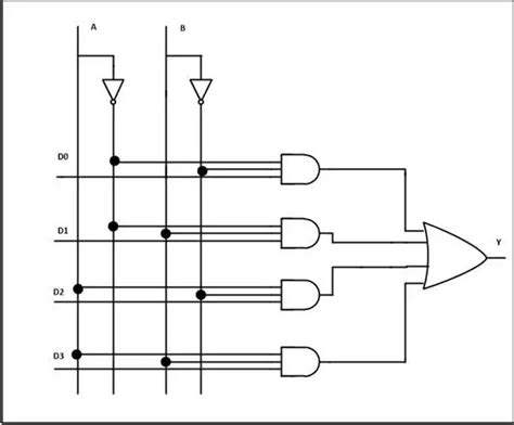
A multiplexer operates by using selection lines to choose one of the input lines and connect it to the output. The number of selection lines determines the maximum number of inputs the multiplexer can handle. For example, a multiplexer with two selection lines (S1 and S0) can handle up to four inputs (I0, I1, I2, and I3).
The truth table below illustrates the operation of a 4-to-1 multiplexer:
| S1 | S0 | Output |
|---|---|---|
| 0 | 0 | I0 |
| 0 | 1 | I1 |
| 1 | 0 | I2 |
| 1 | 1 | I3 |
When S1 and S0 are both 0, the multiplexer selects input I0 and connects it to the output. Similarly, when S1 is 0 and S0 is 1, input I1 is selected, and so on.

Types of Multiplexers
There are several types of multiplexers available, each with its own unique characteristics and applications. Some of the most common types include:
2-to-1 Multiplexer
A 2-to-1 multiplexer has two input lines (I0 and I1) and one selection line (S). It selects between the two inputs based on the state of the selection line.
4-to-1 Multiplexer
A 4-to-1 multiplexer has four input lines (I0, I1, I2, and I3) and two selection lines (S1 and S0). It selects one of the four inputs based on the combination of the selection lines.
8-to-1 Multiplexer
An 8-to-1 multiplexer has eight input lines (I0 to I7) and three selection lines (S2, S1, and S0). It selects one of the eight inputs based on the combination of the selection lines.
16-to-1 Multiplexer
A 16-to-1 multiplexer has sixteen input lines (I0 to I15) and four selection lines (S3, S2, S1, and S0). It selects one of the sixteen inputs based on the combination of the selection lines.

Multiplexer IC Packages and Pinouts
Multiplexer ICs are available in various packages, such as DIP (Dual Inline Package), SOIC (Small Outline Integrated Circuit), and TSSOP (Thin Shrink Small Outline Package). The package choice depends on factors such as the number of inputs, output drive capability, and the intended application.
Here’s an example pinout for a 74HC151, a popular 8-to-1 multiplexer IC in a 16-pin DIP package:
| Pin | Function |
|---|---|
| 1 | I0 |
| 2 | I1 |
| 3 | I2 |
| 4 | I3 |
| 5 | I4 |
| 6 | I5 |
| 7 | I6 |
| 8 | I7 |
| 9 | S2 |
| 10 | S1 |
| 11 | S0 |
| 12 | ~E |
| 13 | Y |
| 14 | VCC |
| 15 | NC |
| 16 | GND |

Applications of Multiplexers
Multiplexers find applications in a wide range of digital systems, including:
Data Routing
Multiplexers are used to route data from multiple sources to a single destination, such as in computer networks, telecommunications systems, and data acquisition systems.
Signal Switching
Multiplexers can switch between multiple analog or digital signals, making them useful in applications such as audio and video switching, sensor selection, and multi-channel data logging.
Logic Function Implementation
Multiplexers can be used to implement various logic functions, such as AND, OR, and XOR gates, by carefully selecting the input signals and the selection lines.
Time-Division Multiplexing
Multiplexers are used in time-division multiplexing (TDM) systems, where multiple signals are interleaved in time to share a single transmission channel, such as in digital telephone systems and satellite communications.
Multiplexer IC Selection Criteria
When choosing a multiplexer IC for your application, consider the following factors:
-
Number of inputs: Choose a multiplexer with the required number of input lines based on your application needs.
-
Switching speed: Ensure that the multiplexer’s switching speed is fast enough for your application. High-speed multiplexers are available for demanding applications.
-
Output drive capability: Consider the load that the multiplexer needs to drive and choose an IC with adequate output drive capability.
-
Power consumption: If power efficiency is a concern, opt for low-power multiplexer ICs, such as those in the CMOS family.
-
Package type: Select a package that is compatible with your PCB design and assembly process.
Multiplexer Circuit Design Considerations
When designing circuits with multiplexer ICs, keep the following considerations in mind:
-
Input signal levels: Ensure that the input signal levels are compatible with the multiplexer’s input voltage range.
-
Output loading: Make sure that the multiplexer’s output is not overloaded by the connected circuitry. Use buffers or drivers if necessary.
-
Switching noise: Multiplexers can introduce switching noise due to the rapid changes in the output signal. Use proper grounding, decoupling, and filtering techniques to minimize noise.
-
Unused inputs: Tie unused multiplexer inputs to a known logic level (either high or low) to prevent floating inputs and ensure proper operation.
Frequently Asked Questions (FAQ)
-
What is the difference between a multiplexer and a demultiplexer?
A multiplexer selects one of several input signals and forwards it to a single output, while a demultiplexer does the opposite – it takes a single input signal and distributes it to one of several outputs based on the selection lines. -
Can a multiplexer be used as a simple switch?
Yes, a 2-to-1 multiplexer can be used as a simple single-pole, single-throw (SPST) switch by connecting one input to the desired signal and the other input to ground or a fixed logic level. -
How do I cascade multiplexers to increase the number of inputs?
To cascade multiplexers, connect the outputs of the first-level multiplexers to the inputs of the second-level multiplexer. The selection lines of the first-level multiplexers become additional inputs to the second-level multiplexer. -
What is the propagation delay of a multiplexer?
The propagation delay is the time it takes for a change in the input or selection lines to be reflected at the output. It varies depending on the specific multiplexer IC and can range from a few nanoseconds to several tens of nanoseconds. -
Can multiplexers be used for analog signals?
Yes, analog multiplexers, also known as analog switches, are designed to handle analog signals. They have special features, such as low on-resistance, high off-resistance, and low leakage currents, to ensure accurate transmission of analog signals.
Conclusion
Multiplexer ICs are versatile and essential components in digital electronics, enabling efficient data routing, signal switching, and logic function implementation. By understanding their working principles, types, and applications, you can effectively incorporate multiplexers into your designs and create more compact, efficient, and flexible digital systems. When selecting multiplexer ICs and designing circuits, consider factors such as the number of inputs, switching speed, output drive capability, power consumption, and package type to ensure optimal performance and reliability.


Leave a Reply